
Systems and Methods for Reducing di/dt Using Clock Signals Having Variable Delays

a clock signal and variable delay technology, applied in the direction of digital transmission, generating/distributing signals, instruments, etc., can solve the problems of reducing the current rate (di/dt), emi and/or power supply noise, and undesirable emi and power supply noise, so as to reduce the current rate (di/dt). the effect of reducing the current ra

Inactive Publication Date: 2008-06-12
KK TOSHIBA
View PDF8 Cites 31 Cited by
  • Summary
  • Abstract
  • Description
  • Claims
  • Application Information

AI Technical Summary

Benefits of technology

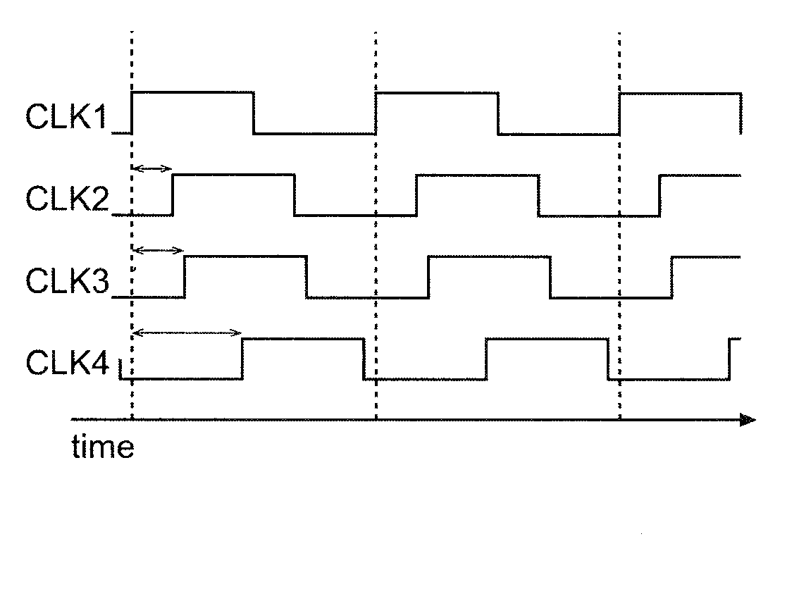
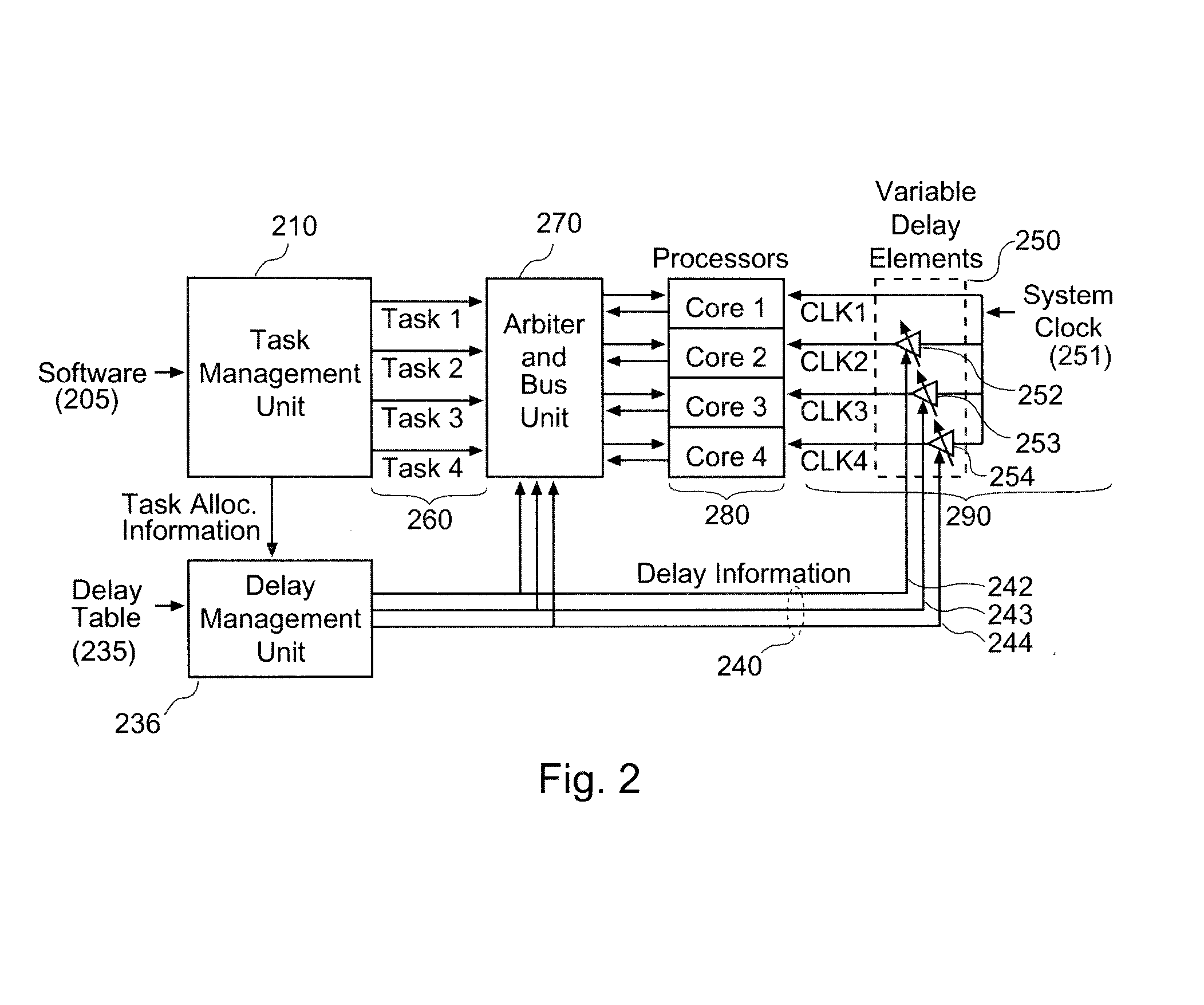
The invention is about managing power consumption in an integrated circuit to reduce the rate of change of current (di / dt) in the integrated circuit. One way to do this is by using a timing system that provides each task processing unit with a corresponding operating clock signal, and imparting variable delays to the clock signals to cause the tasks to be executed with corresponding phase shifts. This allows non-adjacent task processing units to receive consecutive clock signals. The invention also includes a task management unit that determines which tasks are to be executed and assigns them to specific task processing units based on the delays selected by the delay management unit. The delay management unit determines the desired delays by looking up the set of tasks in a look-up table or reading an associated set of delays from the entry. The technical effect of the invention is to reduce power consumption and improve the performance of integrated circuits.

Problems solved by technology

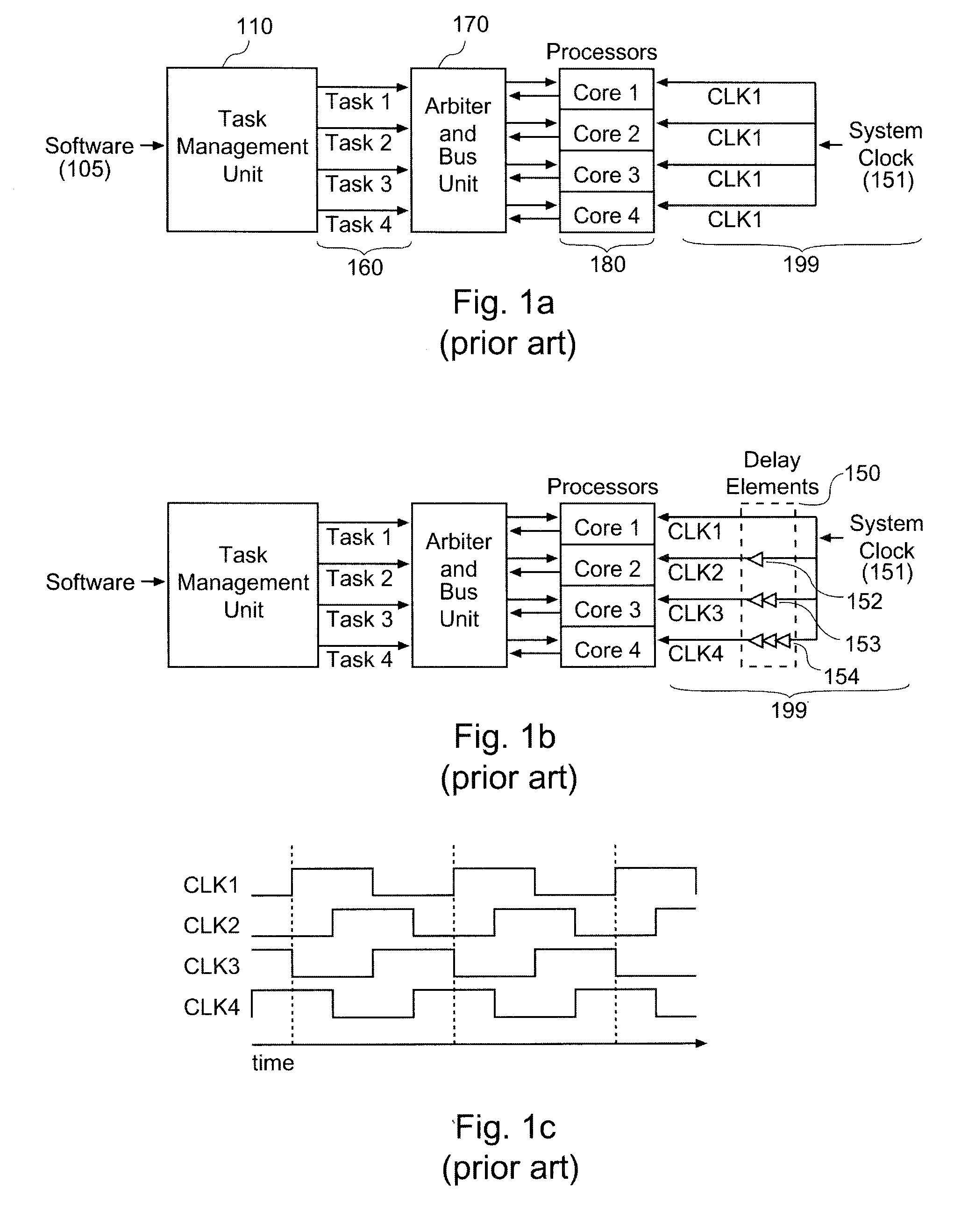
The high rate of change of the current (high di / dt) may cause electromagnetic interference (EMI) and / or noise in the power supply.
Both EMI and power supply noise are undesirable.
The increased clock frequencies make the processors more susceptible to EMI and power supply noise.
These decreased power supply voltages also make the integrated circuits more susceptible to EMI and power supply noise.

Method used


Image

  • Systems and Methods for Reducing di/dt Using Clock Signals Having Variable Delays
  • Systems and Methods for Reducing di/dt Using Clock Signals Having Variable Delays
  • Systems and Methods for Reducing di/dt Using Clock Signals Having Variable Delays

Examples


Embodiment Construction

[0027]One or more embodiments of the invention are described below. It should be noted that these and any other embodiments described below are exemplary and are intended to be illustrative of the invention rather than limiting.

[0028]Broadly speaking, the invention includes systems and methods for managing power consumption by components in an electronic device, and more particularly to systems and methods for improving power usage characteristics such as the change in current (di / dt) in integrated circuits such as microprocessors.

[0029]One embodiment comprises a multiprocessor system. The system has multiple (e.g., 4) processor cores for executing tasks that are defined by the software being run on the system. A task management unit receives the software instructions and identifies a set of tasks to be executed by the processor cores. The task management unit also determines which of the tasks should be assigned to which of the processor cores. This is repeated for successive sets ...


PUM


Abstract

Systems and methods for managing power consumption in an integrated circuit to reduce the rate of change of current (di / dt) in the integrated circuit. One embodiment comprises a system having multiple processor cores. A timing system provides each of the processor cores with a corresponding operating clock signal. The timing system uses variable delay elements to impart variable delays to the clock signals. A delay management unit determines the delays that should be used by the task processing units in executing their assigned tasks and provides this information to the variable delay elements to set the appropriate delays in each of these elements. The delay information is also provided to a task management unit, which assigns the tasks to specific processor cores based upon the delays selected by the delay management unit, so that consecutively fired processor cores are not adjacent to each other.

Description

BACKGROUND[0001]1. Field of the Invention[0002]The invention relates generally to systems and methods for managing power consumption by components in an electronic device, and more particularly to systems and methods for improving power usage characteristics such as the rate of change of current (di / dt) in integrated circuits such as microprocessors.[0003]2. Related Art[0004]When integrated circuits such as processors are operated, they draw current from a power source. The logic components within an integrated circuit typically operate based on a clock signal, so the current drawn by the integrated circuit may suddenly increase at certain points in the clock cycle (e.g. at the rising edge of each clock cycle.) The high rate of change of the current (high di / dt) may cause electromagnetic interference (EMI) and / or noise in the power supply. Both EMI and power supply noise are undesirable.[0005]Reducing EMI and power supply noise is becoming more and more important in designing electr...

Claims


Application Information

Patent Timeline
Patent Type & Authority Applications(United States)
IPC IPC(8): G06F1/06
CPCG06F1/3203G06F1/10
Inventor YAMAOKA, HIROAKI
Owner KK TOSHIBA
Learn More