Display processing device, display processing method and display control program

a technology of display control and processing method, applied in the direction of static indicating devices, instruments, corner/edge joints, etc., to achieve the effect of simplifying data processing

Inactive Publication Date: 2008-06-12
CASIO COMPUTER CO LTD
View PDF39 Cites 19 Cited by
  • Summary
  • Abstract
  • Description
  • Claims
  • Application Information

AI Technical Summary

Benefits of technology

[0007]The present invention has been made in view of the circumstances mentioned above. Accordingly, the purpose of the present invention is to provide a display processing device, a display processing method and a display control program in which the image display processing can be performed by simpler data processing without needing the complicated file management and data management regarding the image display processing. In accordance with the present invention, there is provided a display processing device for achieving the above-described objects which comprises storage means for storing an image file; display means for displaying an image based on the image file stored in the storage means; and display control means for controlling the display to return directly to a first display state when switched to a second display state upon changing the display sequentially to be significantly different from the first display state, wherein the image from the first display state to the second display state is different from the first display state, based on an image display control information included in the same image file as the image file included in the image displayed on the display means.

Problems solved by technology

However, when sending and receiving images on a wireless communications terminal, namely cellular / mobile phones and the like, and such a display process method is applied, there exists a drawback with the user's transmitting side of the wireless communications terminal whereby the image file corresponding to the image and the display processing information which accompanies the image has to be transmitted as separate data when the user desires to display an image and specify the scroll direction, desires to make an image zoom in to observe a portion of an image or even when desiring to zoom out from a portion of an image to its entirety in the receiver's side of the wireless communications terminal.

Method used


Image

  • Display processing device, display processing method and display control program
  • Display processing device, display processing method and display control program
  • Display processing device, display processing method and display control program

Examples


first embodiment

A. First Embodiment

A-1. Configuration of the First Embodiment

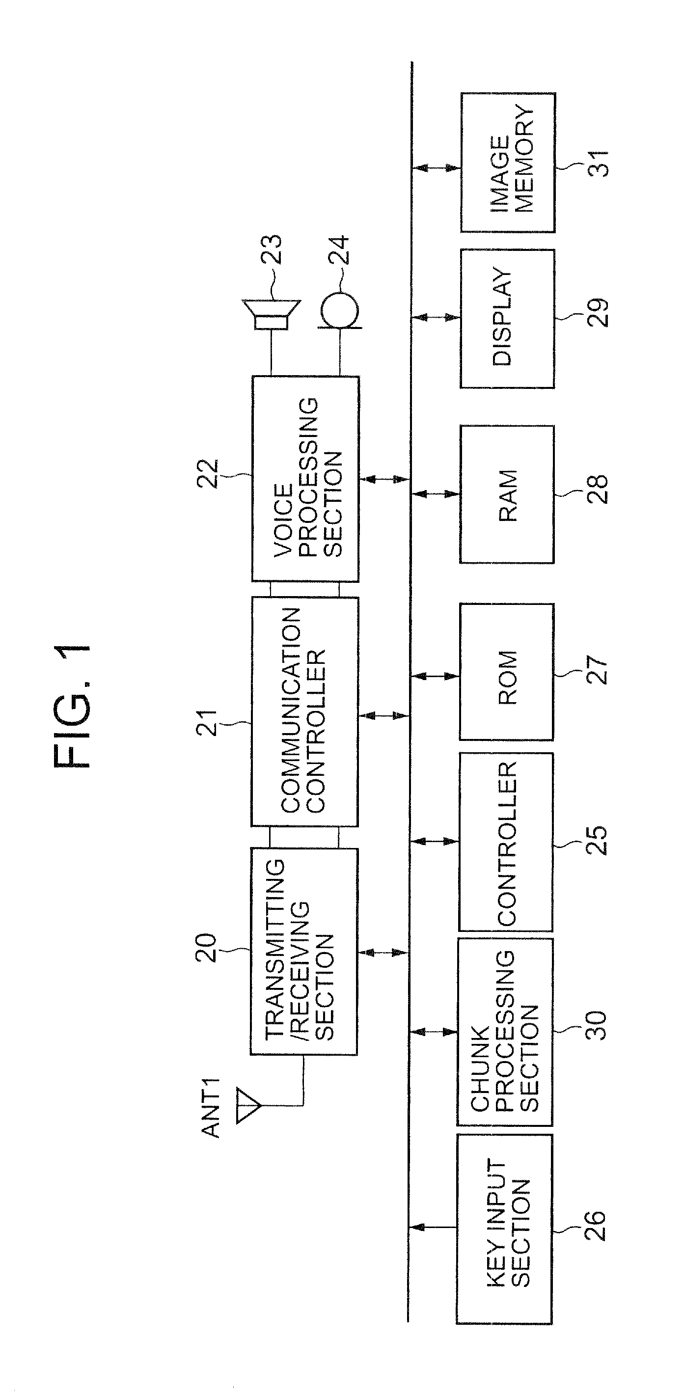
[0042]FIG. 1 is a block diagram showing the configuration of the cellular phone according to the first embodiment of this invention. Referring to FIG. 1, a transmitting and receiving section 20 (hereinafter referred to as “transceiver” for convenience) consists of a frequency conversion section and a modem. In order to carry out base station and wireless communications which are not illustrated, frequency conversion of the electromagnetic waves as well as modulation and demodulation are performed via an antenna ANT1. Next, a communications controller 21 performs telecommunications control based on predetermined transmission methods (for example, Time Division Multiple Access (TDMA), Code-Division Multiple Access (CDMA) and the like). A voice processing section 22 performs encoding / decoding of the audio signal. This audio signal is decoded by the Code Excited Linear Predictor (CELP) encoding method from the communications c...

second embodiment

B. Second Embodiment

B-1. Configuration of the Second Embodiment

[0058]Next, the second embodiment will now be explained. In the second embodiment, which adds to the functions of the first embodiment above, assignment of the parameters in the text chunk at the time of performing display control of the image is enabled. The description of the configuration of the cellular phone 1 is omitted as it is the same as FIG. 1.

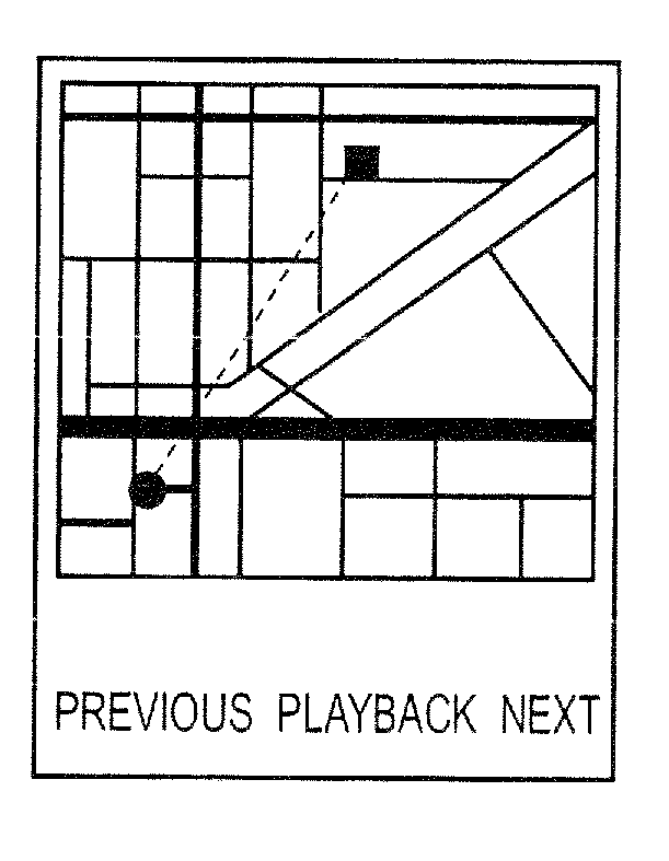
[0059]FIGS. 12A-12D are conceptual diagrams showing an illustrative example of the used text chunk in the second embodiment. In the examples shown in FIGS. 12A-12D, “Command” is used as the keyword. Moreover, as the same value, while containing the text data which indicates what type of image display control is to be performed, further contains the parameters for when performing image display control. For parameters, “PARAMETER1” for directing the playback speed, “PARAMETER2” for directing the playback start coordinates and the playback end coordinates are prepared. The p...

third embodiment

C. Third Embodiment

C-1. Configuration of the Third Embodiment

[0071]Next, the third embodiment of this invention will be explained. In the third embodiment, it is possible to designate the display pixels, when the image is played back, in the text chunk of image file in the function of the above-mentioned first embodiment. Furthermore, when assignment of the display pixels at the time of reproducing the image in the image file text chunk is enabled and the display pixels are not in agreement with the display screen size of the cellular phone, the image is enlarged / reduced automatically. In addition, the description of the configuration of the cellular phone 1 is omitted as it is the same as FIG. 1.

[0072]FIG. 15A is a conceptual diagram showing an illustrative example of the used text chunk in the third embodiment. In FIG. 15A, “Coordinate” is used as the keyword. As this value, the keyword “Command” has a starting point coordinates “x1, y1” to show which portion is displayed by the t...


PUM

PropertyMeasurementUnit
latitudeaaaaaaaaaa
longitudeaaaaaaaaaa
sizeaaaaaaaaaa

Abstract

The image browse function is activated and the image is displayed. When the function key (playback) is depressed, the pointer is placed at the top of the image file chunk corresponding to the displayed image. The operation then judges whether or not the position of the pointer is the text chunk. When the text chunk is discovered by the position of the pointer, the operation judges whether or not the keyword (image display control information) which indicates insertion of the image display control information was inserted and described. When the keyword has been inserted, the operation extracts the keyword and performs display processing of the image according to the keyword (image display control information).

Description

CROSS-REFERENCE TO RELATED APPLICATION[0001]The present application is a Continuation Application of U.S. application Ser. No. 10 / 810,187 filed Jul. 19, 2007, which is based upon and claims the benefit of priority from prior Japanese Patent Application Nos. 2003-088256, filed Mar. 27, 2003 and 2004-047040, filed Feb. 23, 2004, the entire contents of which are incorporated herein by reference.BACKGROUND OF THE INVENTION[0002]1. Field of the Invention[0003]The present invention relates to a display processing device, display processing method and display control program which displays images without performing a particular display control operation.[0004]2. Description of the Related Art[0005]In recent years, a camera (including attachable and detachable types) comprising a communications terminal, such as a cellular / mobile phone and the like, from being able to connect with the Web to receive various multimedia files to improvement in the number of display colors, it is possible to d...

Claims


Application Information

Patent Timeline
Patent Type & Authority Applications(United States)
IPC IPC(8): G06F3/00G06F3/14G06F3/048G06F3/0485G09G5/00G09G5/34G09G5/36H04M1/00H04M1/02
CPCG06F3/14G09G2340/14G09G2340/0407G09G5/346E06B3/721E06B3/5892E06B3/5821E06B3/9636E06B3/99E06B7/30E06B2003/7082
Inventor TAKAHASHI, OHNAGATOMO, SHOICHI
Owner CASIO COMPUTER CO LTD
Why Eureka
Try Eureka