
Labeling system for coil binders

a labeling system and coil binding technology, applied in the direction of identification means, book covers, instruments, etc., can solve the problems of difficult identification of coil binding documents which are shelved or stacked, the edge of the coil binding is visible, and the coil binding is difficult to identify the coil binding. the effect of structural rigidity

Inactive Publication Date: 2008-06-19
GNESA ARIC M
View PDF9 Cites 4 Cited by
  • Summary
  • Abstract
  • Description
  • Claims
  • Application Information

AI Technical Summary

Benefits of technology

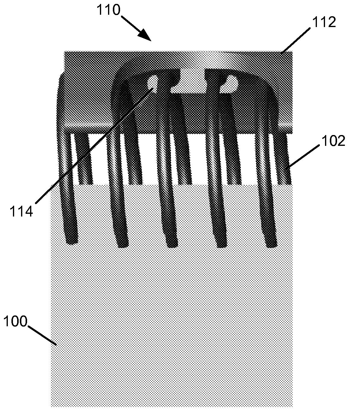
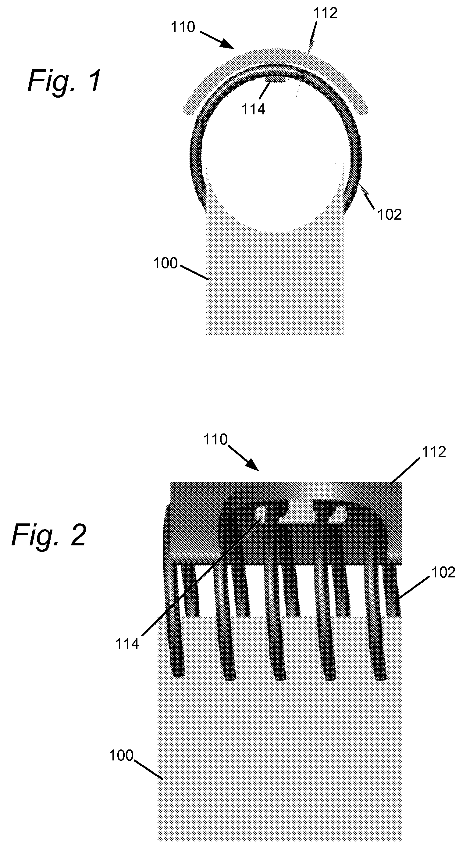
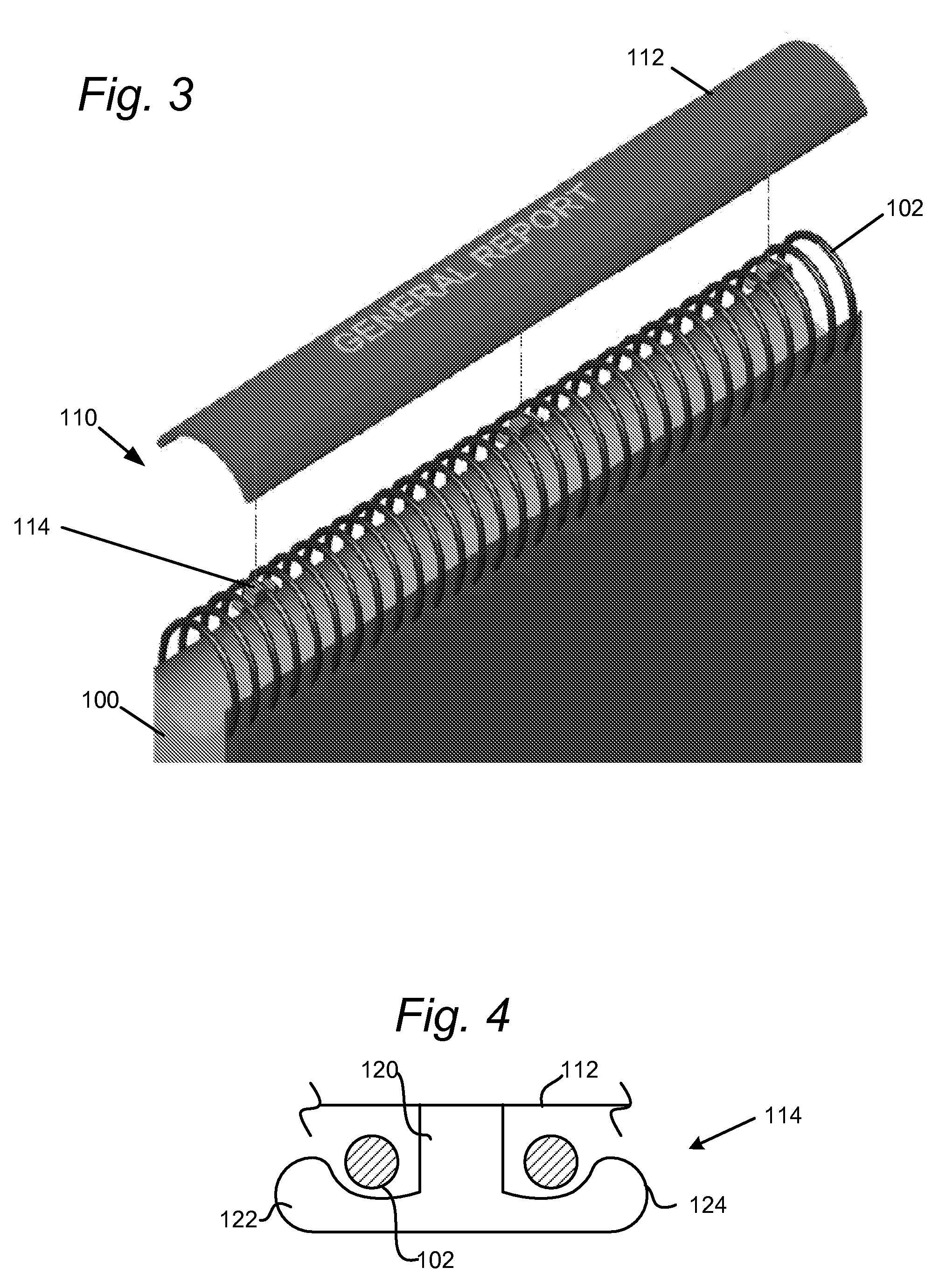
[0008]The present invention, roughly described, relates to a labeling member which attaches to the coil used for the coil binding of documents. The member may be affixed as an aftermarket upgrade to existing coil binding products. In embodiments, the member serves at least two functions. First, the member presents a face along the edge of a coil which may be marked or labeled to allow identification of the coil bound document when shelved or stacked. Second, the member adds structural rigidity to the bound document when placed vertically on a shelf by making the coil more rigid.

Problems solved by technology

While an effective and efficient method for securely binding documents, coil binding has a disadvantage in that, when shelved or stacked side-by-side with other bound documents, only the coil bound edge of the document is visible.
Accordingly, it is difficult to identify coil bound documents which are shelved or stacked.

Method used


Image

  • Labeling system for coil binders
  • Labeling system for coil binders
  • Labeling system for coil binders

Examples


Embodiment Construction

[0019]The present invention will now be described with reference to FIGS. 1-10, which in embodiments relates to a labeling system for coil bound documents. It is understood that the present invention may be embodied in many different forms and should not be construed as being limited to the embodiments set forth herein. Rather, these embodiments are provided so that this disclosure will be thorough and complete and will fully convey the invention to those skilled in the art. Indeed, the invention is intended to cover alternatives, modifications and equivalents of these embodiments, which are included within the scope and spirit of the invention as defined by the appended claims. Furthermore, in the following detailed description of the present invention, numerous specific details are set forth in order to provide a thorough understanding of the present invention. However, it will be clear to those of ordinary skill in the art that the present invention may be practiced without such ...


PUM


Abstract

A labeling member is disclosed which attaches to the coil used for the coil binding of documents. The member may be affixed as an aftermarket upgrade to existing coil binding products. In embodiments, the member serves at least two functions. First, the member presents a face along the edge of a coil which may be marked or labeled to allow identification of the coil bound document when shelved or stacked. Second, the member adds structural rigidity to the bound document when placed vertically on a shelf by making the coil more rigid.

Description

BACKGROUND OF THE INVENTION[0001]1. Field of the Invention[0002]The present invention is directed to a labeling system for coil binders, and in particular to an attachment which affixes to a coil binding of a coil binder.[0003]2. Description of the Related Art[0004]Coil binding is a popular means of binding a number of pages together to create reports, studies, and other documents. A coil bound document is formed by initially punching holes along an edge of the document. Then, a flexible coil is spun, or threaded, helically into the document through the punched holes. Most coils are made from a variety of flexible materials, such as PVC plastic or metal, and are available in wide range of diameters, pitches, and lengths to fit different binding needs.[0005]While an effective and efficient method for securely binding documents, coil binding has a disadvantage in that, when shelved or stacked side-by-side with other bound documents, only the coil bound edge of the document is visible....

Claims


Application Information

Patent Timeline
IPC IPC(8): B42F13/40
CPCB42B5/12B42P2221/02B42F3/06B42D3/008
Inventor GNESA, ARIC M.
Owner GNESA ARIC M
Learn More