Eureka AIR delivers breakthrough ideas for toughest innovation challenges, trusted by R&D personnel around the world.

Method and apparatus for securing connecting ferrules

Inactive Publication Date: 2008-06-19
INTELLIGENT DESIGN GROUP
View PDF16 Cites 19 Cited by
  • Summary
  • Abstract
  • Description
  • Claims
  • Application Information

AI Technical Summary

Problems solved by technology

The aforementioned methods create sharp and inconsistent deformations, indentations, and creases in the ferrule.
In addition, the non-uniform shape of the reduced terminal creates voids between the terminal and the wires leading to possible fouling and corrosion from moisture migration into the voids.
Still yet, the unpredictable variations formed by these methods of deformation create connections with equally unpredictable and inferior mechanical strength.
Less common and more exotic methods do achieve symmetric connections such as hexagonal or square shapes, but still do not achieve finished connections having a substantially circular cross-section and thus suffer from the aforementioned problems to some degree.
The method and apparatus of the Forney patent is fundamentally flawed in that the curved portions of the male and female dies have substantially equal radii of curvature.
Using a substantially equal radius in the male die also creates extremely thin and fragile lateral edges along the width of the upper die.
Exposing these edges to the forming pressures between the dies will cause them to break down and fail.
It has been found in practice that pressing a ferrule into such a sharply tapering transition will cause it to bind and effectively jam the mechanism, damage the ferrule, and result in a failure to complete the forming process.

Method used


Image

  • Method and apparatus for securing connecting ferrules
  • Method and apparatus for securing connecting ferrules
  • Method and apparatus for securing connecting ferrules

Examples


Embodiment Construction

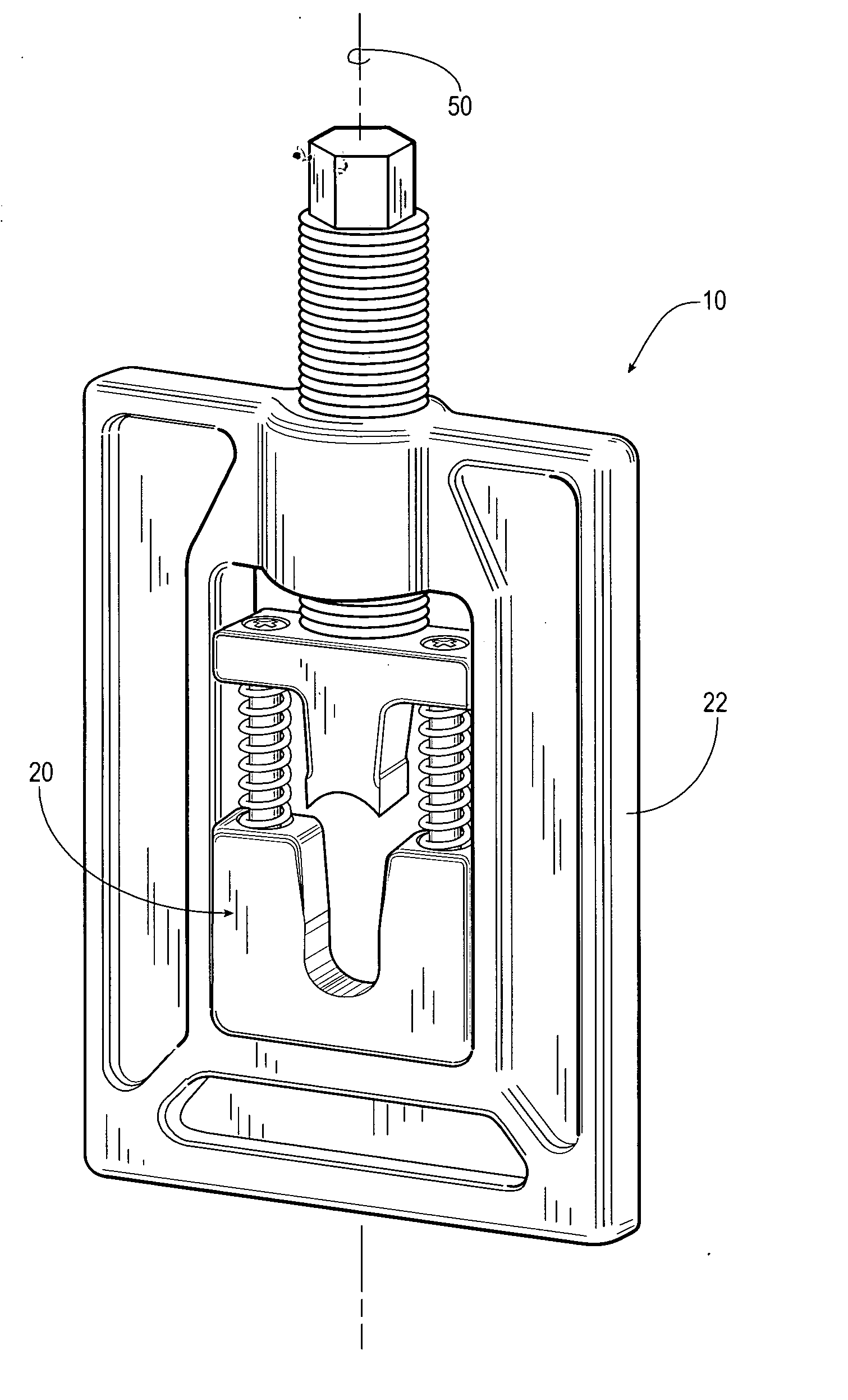
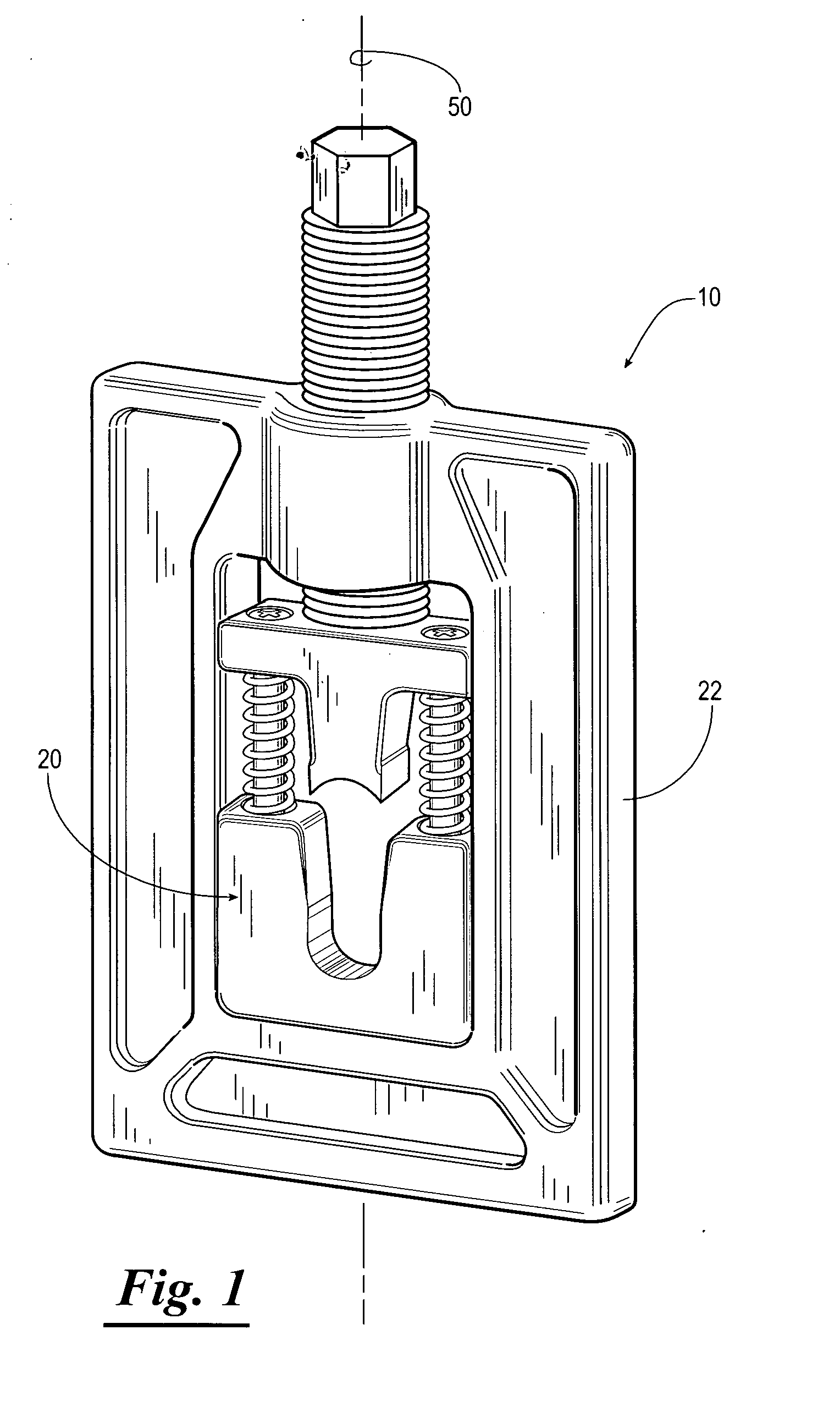
[0019]Referring now to the drawings, and more particularly to FIGS. 1 and 2, a ferrule securing assembly 10 constructed in accordance with the present invention is shown in FIG. 1. An exemplary wire terminal 12 is shown in FIG. 2 after having been secured to the terminal end of a group of wires 14 with the ferrule securing assembly 10. The wire terminal 12 shown in FIG. 2 is a standard blade-type connector having a connection portion 16 and a ferrule 18. The wire terminal 12 and the wires 14 are examples of items that may be utilized in accordance with the present invention and are in no way intended to be limiting.

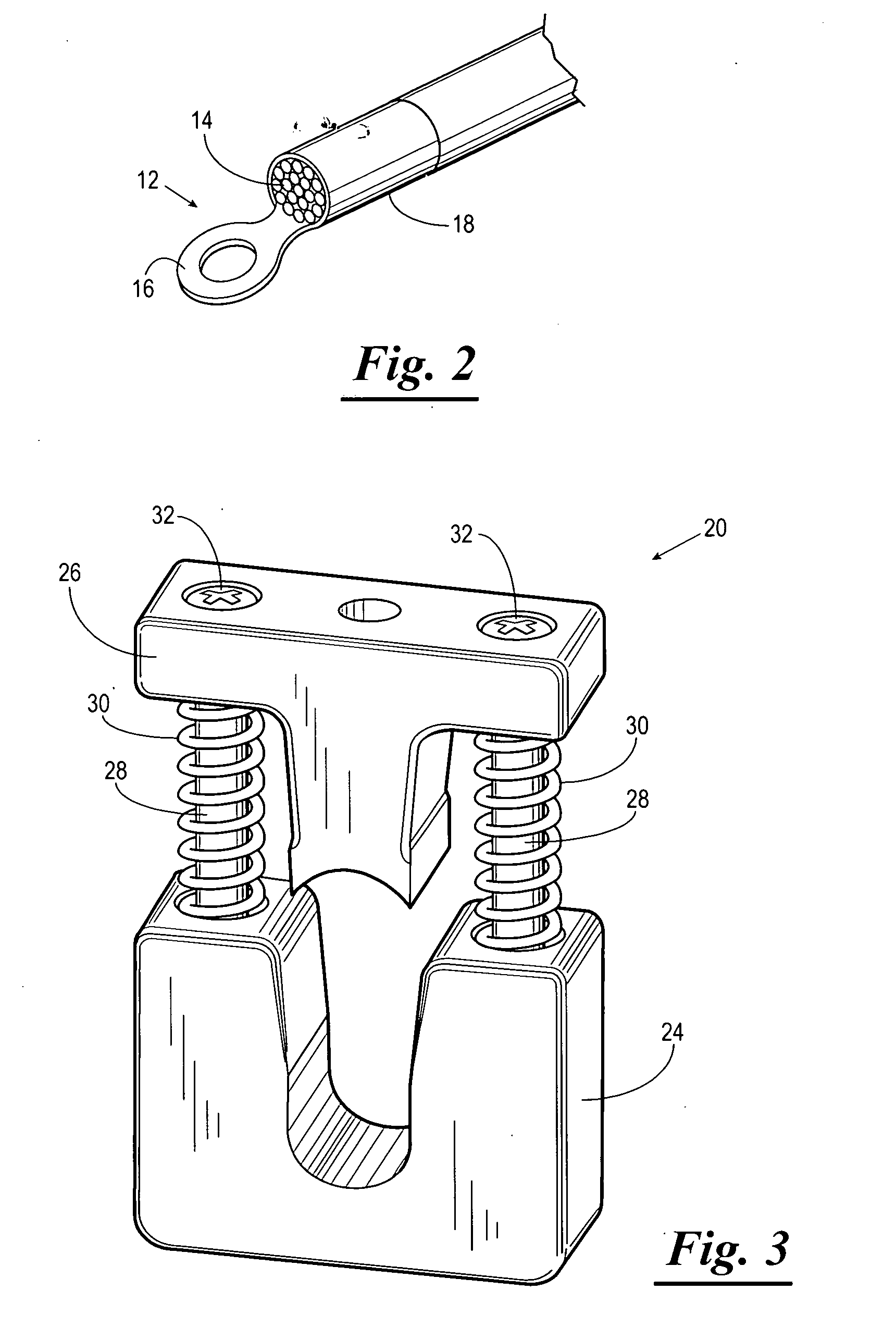
[0020]The ferrule reducing assembly 10, as shown in FIG. 1, includes a die set assembly 20 and an actuating assembly 22. The actuating assembly 22 is used to apply force to the die set assembly 20, and the die set assembly 20 controls the geometric process of reducing the ferrule 18 to make the desired connection.

[0021]Referring now to FIGS. 3-7, the die set assembly 20 i...


PUM

PropertyMeasurementUnit
Fractionaaaaaaaaaa
Fractionaaaaaaaaaa
Fractionaaaaaaaaaa

Abstract

A ferrule securing assembly including a die set assembly for reducing a cylindrical ferrule. The die set assembly having a female die and a male die. The female die having a female die opening sequentially defined by a tapered section, a parallel section, and a concave seat. The male die having a concave die face with at least two lateral edges, a medial area, and a radius of curvature. The male die is receivable in the female die opening to move the ferrule through the tapered section so as to forge the ferrule into a substantially oval shape, to move the oval shaped ferrule through the parallel section, and to compress the oval shaped ferrule between the concave die face and the concave seat to forge the oval shaped ferrule into a substantially cylindrical shape. The radius of curvature of the concave die face being greater than the radius of curvature of the concave seat such that contact between the ferrule and the concave die face is shifted from the lateral edges of the concave die face to the medial area of the concave die face as the ferrule is moved through the tapered section.

Description

BACKGROUND OF THE INVENTION[0001]1. Field of the Invention[0002]The present invention relates generally to a method and apparatus for securing a connector employing a connecting body such as a ferrule over an inner member such as a wire. The present invention also has general application in making mechanically secure connections using connectors having a connecting body requiring shrinkage or mechanical deformation to be secured over an inner load carrying member, such as a guy wire or support cable. More specifically, but not by way of limitation, the present invention is directed to a method and apparatus for connecting ferrules such that the connected ferrule is substantially circular in shape but with sufficiently reduced cross-sectional area so as to achieve a circumferentially tight fit around the inner members.[0003]2. Brief Description of Related Art[0004]The field of wire termination utilizes a number of common practices to achieve electrically and mechanically efficient co...

Claims


Application Information

Patent Timeline
IPC IPC(8): B21D37/10
CPCH01R43/058Y10T29/49929Y10T29/53996Y10T29/53235
Inventor WIGHTMAN, WILLIAM A.CLINGERMAN, JAMES C.
Owner INTELLIGENT DESIGN GROUP
Why Eureka
Eureka Blog
Learn More