Mobile, expandable, inhabitable structure

a technology of expanding and expanding, which is applied in the direction of vehicles, building types, buildings with living accommodation, etc., can solve the problems of not increasing the size of the end wall, requiring manual intervention to deploy the end wall, and relatively small siz

Inactive Publication Date: 2008-06-19
BONEBRAKE JEFFREY M
View PDF1 Cites 30 Cited by
  • Summary
  • Abstract
  • Description
  • Claims
  • Application Information

AI Technical Summary

Benefits of technology

[0009]An objective of the present invention is to provide a room extension system intended for use with large wheeled structures such as a recreational vehicle or semi-trailer that is fully automated during the deployment process. This system will also automatically deploy a support/stability device. The unique feature of the system is that it requires no manual intervention for deployment or retraction. The system features a deployable/expandable and retractable structure, the movement of which is controlled by the use of a Programmable Logic Controller (PLC) that coordinates the hydraulic, pneumatic and or electric actuation devices. The system inclu

Problems solved by technology

The most obvious limitation however, is their relatively small size resulting from the width restrictions of a normal road or highway.
While this invention does expand the usable space, it does not increase it enough to dramatically enhance perceived living space.
The major drawback to this desi

Method used


Image

  • Mobile, expandable, inhabitable structure
  • Mobile, expandable, inhabitable structure
  • Mobile, expandable, inhabitable structure

Examples


Embodiment Construction

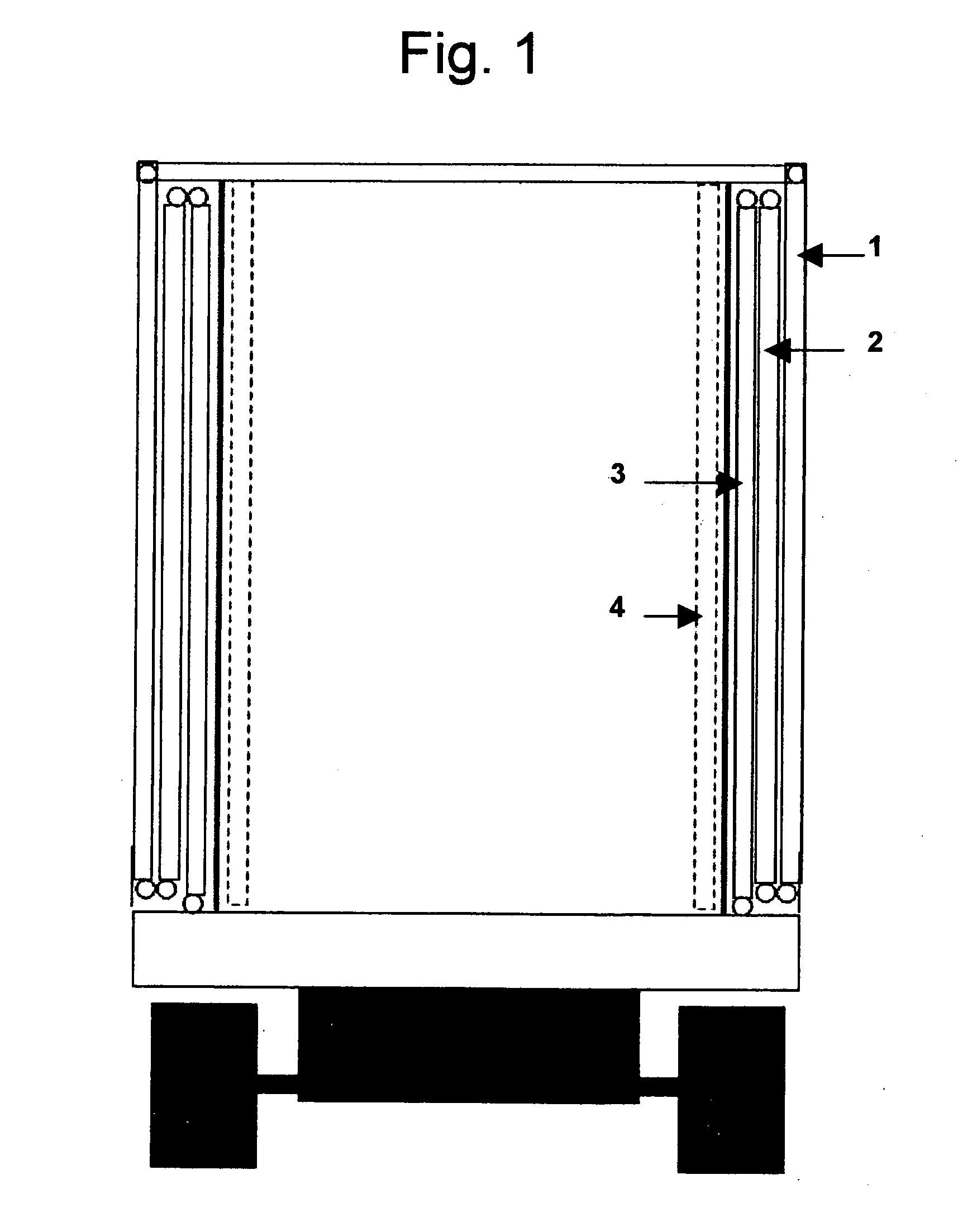
[0011]FIG. 1 is a cross-sectional view showing the collapsed state of the base trailer. The panel 1 forms the exterior wall in the collapsed state and will form the roof panel in the expanded state. Panels 2 and 3 are interior in the collapsed state and form the side and floor panels respectively in the expanded state. In the Expanded state panel 4 will pivot to form the end walls of the expansion.

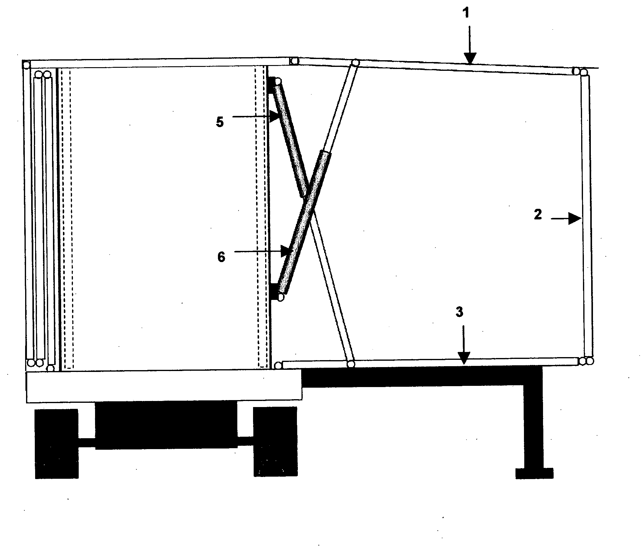
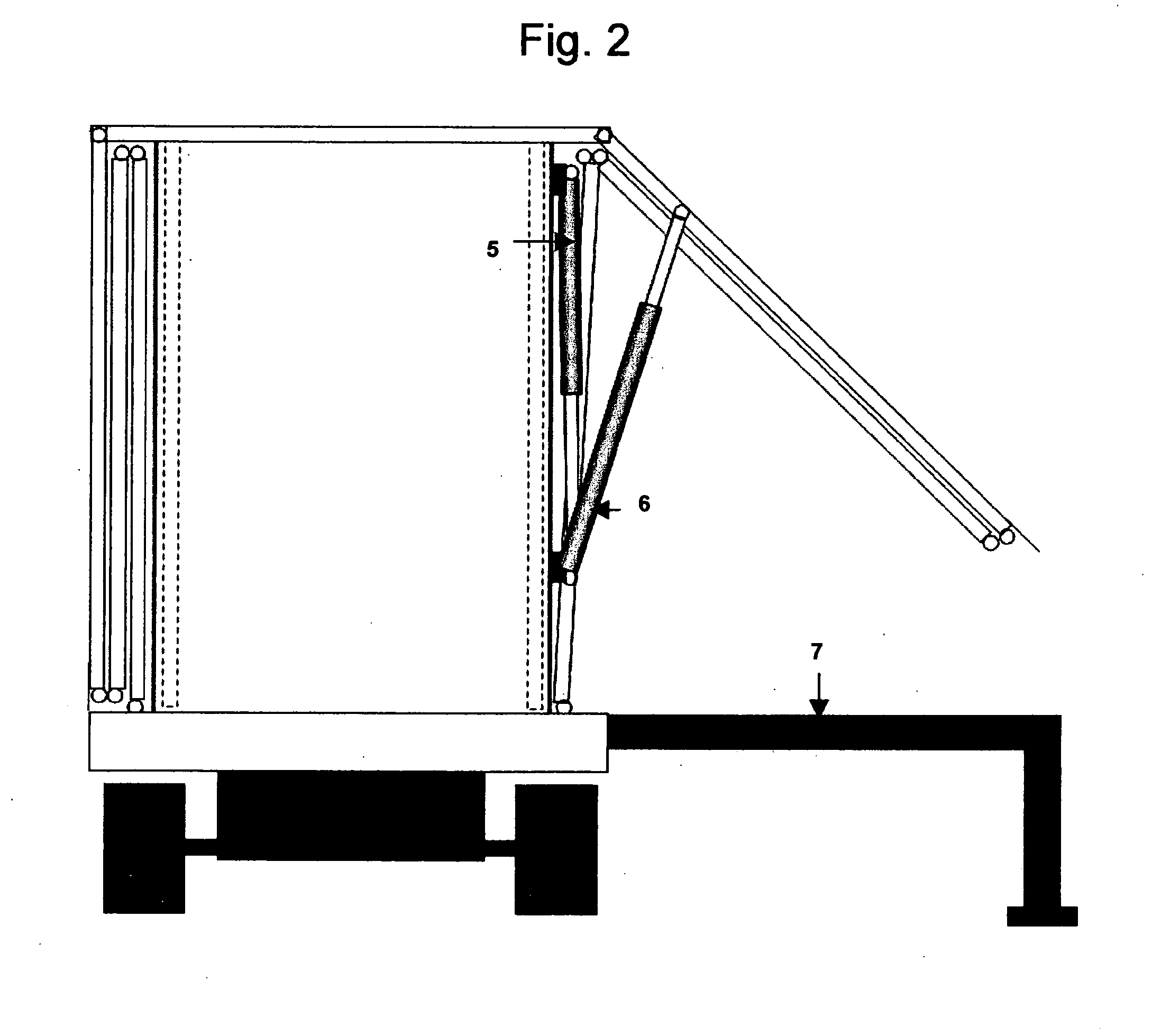
[0012]Deployment to the expanded state, beginning with the support structure, will only require a push of a button on the PLC. FIG. 2 shows the extending support structure 7 that will be further described in FIGS. 10-13. It also shows the beginning of the deployment process, which is accomplished with the use of hydraulic, pneumatic or electric driven actuators 5 and 6. As previously noted, the entire expansion process is automated and would begin with a simple push-button devise.

[0013]FIG. 3 depicts the structure in a further state of expansion. Note that while actuator 6 continues to ext...


PUM


Abstract

The invention encompasses an entirely automated room extension intended for larger wheeled structures such as a Recreational Vehicle or a semi trailer that has been modified to form an office or semi-permanent emergency shelter. The extension, having substantially hinged, folding, rigid panels that in the collapsed state are stacked flush forming the exterior surface and with a simple push button will automatically deploy a supporting structure and then automatically expand the panels to form a solid enclosure of usable interior space. A programmable logic controller will activate the extension and contraction of several actuators in such order as to deploy and collapse the enclosure by push button with no manual intervention.

Description

CROSS-REFERENCE TO RELATED APPLICATIONS[0001]Not ApplicableSTATEMENT REGARDING FEDERALLY SPONSORED RESEARCH OR DEVELOPMENT[0002]Not ApplicableREFERENCE TO SEQUENCE LISTING, A TABLE, OR A COMPUTER PROGRAM LISTING COMPACT DISC APPENDIX[0003]Not ApplicableBACKGROUND OF THE INVENTION[0004]The present invention relates to a mobile, expandable, inhabitable structure that could be utilized in the recreational vehicle industry or serve as medium-term housing for victims of a disaster.[0005]Recreational vehicles are popular because they provide the owner with many of the comforts they enjoy at home. The most obvious limitation however, is their relatively small size resulting from the width restrictions of a normal road or highway. There have been many variations of slide-out room extensions but none of those provide the increased space benefits of this new invention.[0006]U.S. Pat. No. 5,800,002 to Tiedge increases the size of a recreational vehicle by use of an expandable room. While this ...

Claims


Application Information

Patent Timeline
IPC IPC(8): E04H15/08
CPCE04B1/3444B60P3/34
Inventor BONEBRAKE, JEFFREY M.
Owner BONEBRAKE JEFFREY M
Why Eureka
Try Eureka