
System for Displaying Photographs

a technology for displaying systems and photographs, applied in the field of systems for displaying photographs, can solve the problems of not providing a way to display more than a single photograph at a time, each providing no way to support the display device, and not providing for a display device that is easy to us

Inactive Publication Date: 2008-06-19
SNAP GALLERY +1
View PDF10 Cites 32 Cited by
  • Summary
  • Abstract
  • Description
  • Claims
  • Application Information

AI Technical Summary

Benefits of technology

[0008]One embodiment of the invention is a system for supporting photographs. The system includes at least one horizontal member having a hollow portion, and two or more vertical members having a shaped cross section and configured for support by the at least one horizontal member, wherein the at least one horizontal member is configured for mounting in a primarily horizontal orientation and the vertical members are configured for mounting in a vertical orientation, the vertical members also having a portion for mounting in the hollow portion of one or more of the at least one horizontal member, and the vertical members are configured for supporting photographs.

Problems solved by technology

For example, U.S. Pat. Nos. 3,041,762 and 7,100,317 each provide a device for displaying a picture or photograph, but do not provide for a way to display more than a single photograph at a time.
In addition, each provides no way to support the display device other than directly onto a horizontal surface, such as a table or a shelf.
Other prior art devices provide for more than a single photograph or object, but do not provide for a display device that is easy to use, i.e., to change the objects, also provide for a way to hold the devices securely.
In addition, this disclosure does not specify how the horizontal members are supported on the vertical members, other than very heavy and awkward-looking support members.
The covers must be fully inserted from the side, and thus are not easily removed from the frame.
In addition, there is no detail on how the frame is assembled other than that the members are made of solid wood pieces.
These frames would thus be heavy and, because of the shape of method of making the slots, would also be difficult to use.
This system would not enable a user to support photos or art work independently, since each object would still require a frame or other support.

Method used


Image

  • System for Displaying Photographs
  • System for Displaying Photographs
  • System for Displaying Photographs

Examples


first embodiment

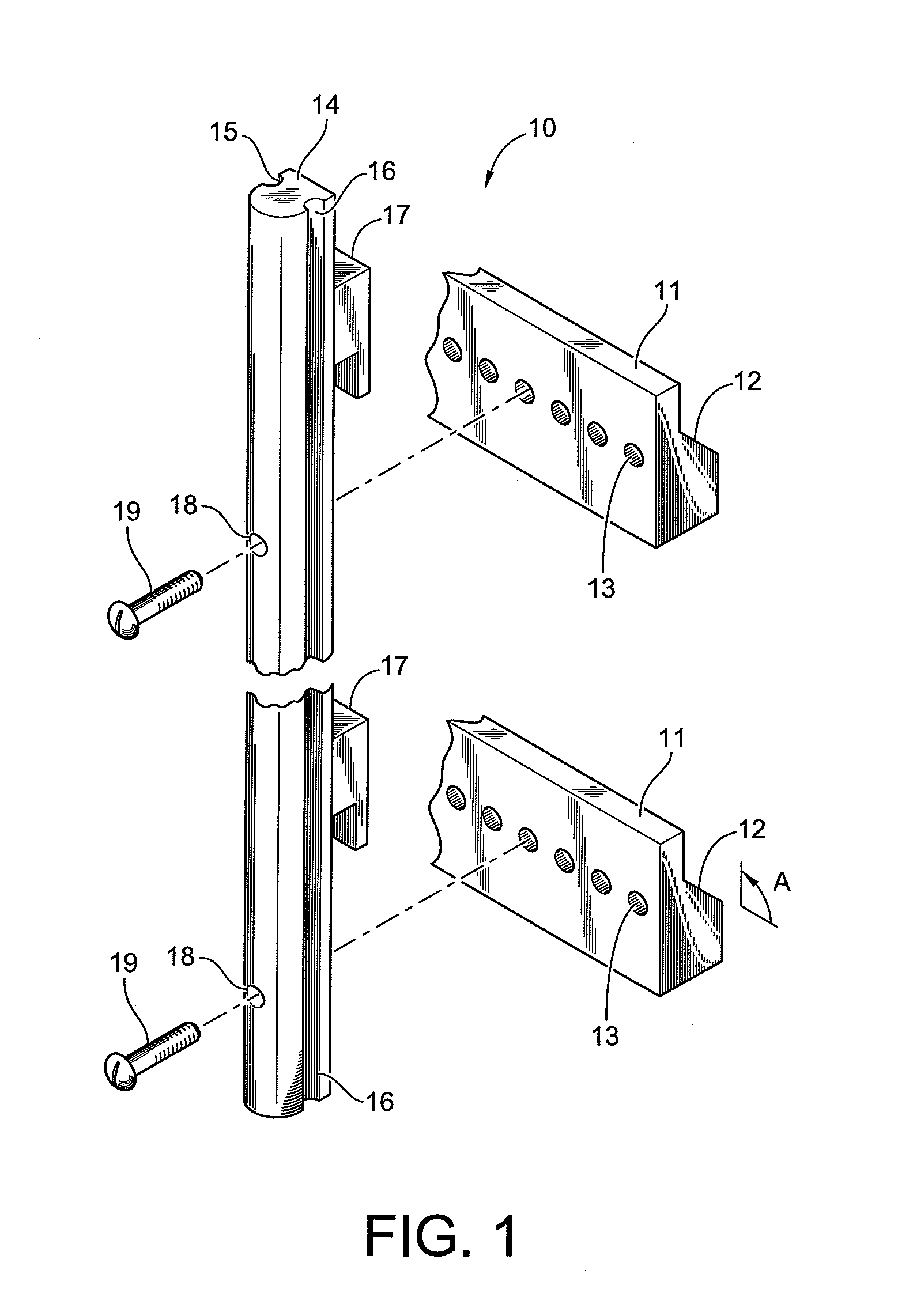
[0025]There are many ways to use this invention, a few of which are described below. FIG. 1 illustrates a system 10 for supporting and displaying photographs. The system includes two or more horizontal members 11, each of which has a continuous horizontal notch 12 and two or more drilled holes 13. It is preferred that two horizontal members 11 are used to support each vertical member 14, as shown. The horizontal members 11 are fastened to a wall (not shown) with anchors, screws, or other fasteners that are inserted through holes 13. The continuous notches 12 of the horizontal members provide a space adjacent the wall for a tab 17 from two or more vertical members 14. The notches may be made at a right angle to the vertical, or may be made at an angle A, such as a 45° degree angle to the horizontal, as shown.

[0026]Vertical members 14 preferably include notches 15, 16 on either side. The notches are preferably continuous vertical notches along the length of the vertical member. Becaus...

second embodiment

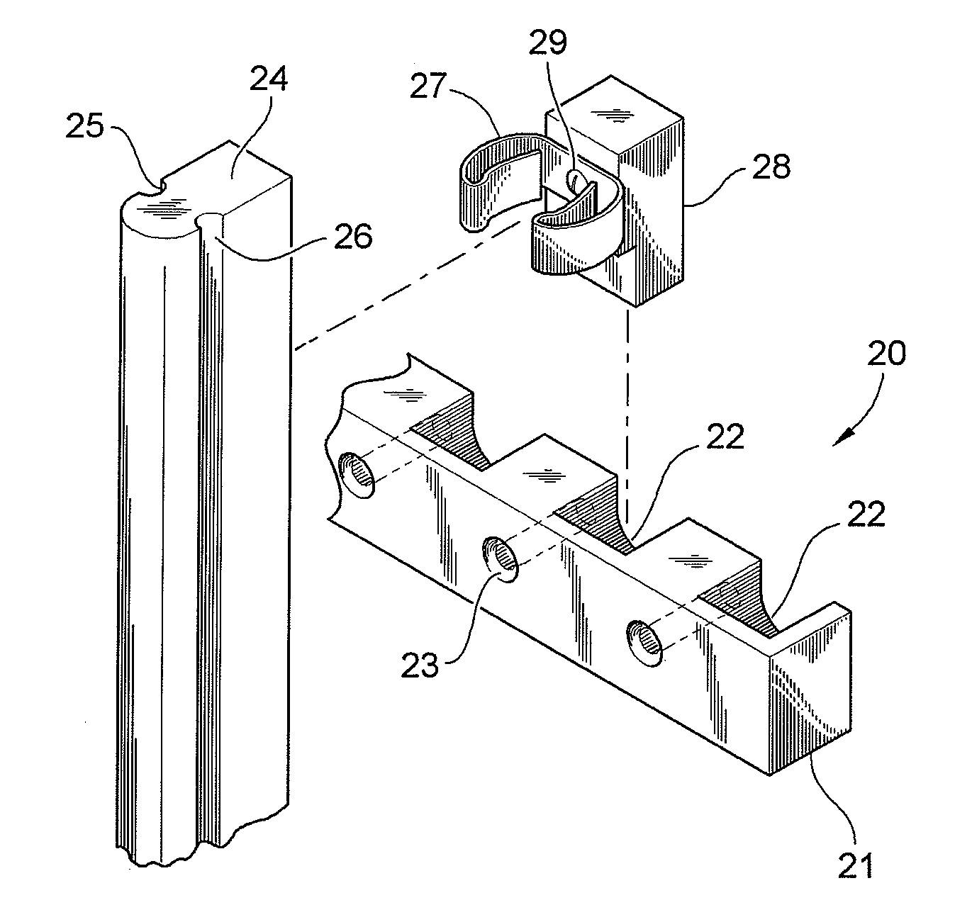
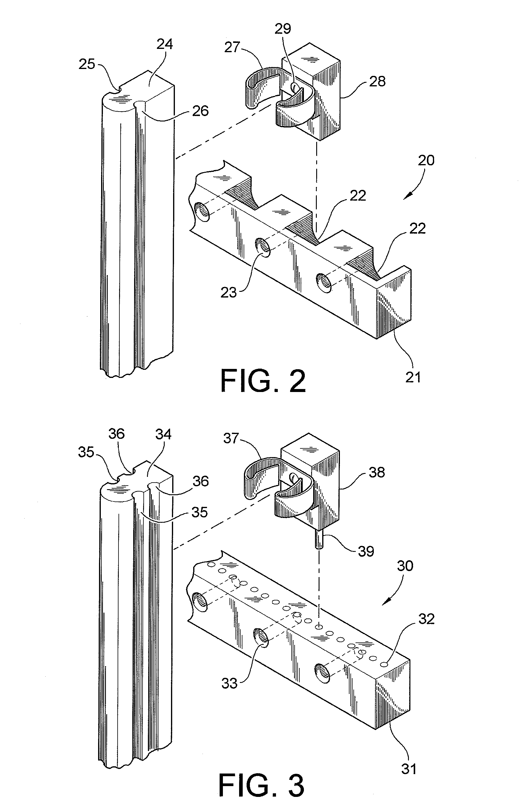
[0028]FIG. 2 illustrates components useful in a display system 20. In this embodiment, horizontal members 21 have discrete notches 22 instead of a continuous notch as in the previous embodiment. The horizontal members 21 also have drilled holes 23 for fastening to a vertical display surface, such as a wall. The vertical members 24 include continuous vertical notches 25, 26. Each vertical member is secured to one or more horizontal members using one or more clamps 27, tabs 28, along with fasteners 29 that secure each clamp 27 to tab 28. Clamp 27 is preferably a flex spring clamp, such as a hose clamp or a spring steel clamp. These clamps are typically made from thin spring steel or flexible plastic. The clamp may then be mounted to the appropriate position on the vertical member 24, and the clamp is secured to the horizontal member 21 by placing tab 28 into the desired notch 22. Alternatively, the tab 28 may fit very tightly into notch 22, and the vertical member may then be joined t...


PUM


Abstract

A system for displaying photographs is disclosed. The system includes one or more horizontal members or bars that are secured to a wall, such as a wall of a house. The horizontal members are preferably immovably secured, as by wall anchors or nails. The horizontal members preferably include a profile, such as a shaped, hollow cross-sectional area, that is configured to mount two or more vertical members. Two or more vertical members or bars are then secured to the horizontal members. The vertical members may be mounted using the profiles, channels, or grooves of the horizontal members. They may be mounted using a tab or a clamp, such as a spring clamp. The vertical members preferably also include continuous, vertical grooves on their sides, for placing photographs into the grooves for display.

Description

FIELD OF THE INVENTION[0001]This invention generally relates to a system for mounting photographs and other images for display.BACKGROUND OF THE INVENTION[0002]The present invention is directed to systems for displaying photographs and similar items in a pleasing manner. The prior art shows several examples of systems for holding or displaying objects, but none has the desired degree of simplicity and reliability that is sought in the present invention. For example, U.S. Pat. Nos. 3,041,762 and 7,100,317 each provide a device for displaying a picture or photograph, but do not provide for a way to display more than a single photograph at a time. In addition, each provides no way to support the display device other than directly onto a horizontal surface, such as a table or a shelf.[0003]Other prior art devices provide for more than a single photograph or object, but do not provide for a display device that is easy to use, i.e., to change the objects, also provide for a way to hold th...

Claims


Application Information

Patent Timeline
Patent Type & Authority Applications(United States)
IPC IPC(8): A47G1/16G09F7/08G09F1/10A47F5/08
CPCA47G1/16G09F15/0068G09F7/08G09F1/10
Inventor ZLOTOCHA, PETER S.
Owner SNAP GALLERY
Learn More