System and method for controlling microgrid

a micro-grid and micro-control technology, applied in the field of micro-grids, can solve the problems of slow response of approaches, inability to regulate frequency, and high cost of approaches, and achieve the effect of regulating voltage but not frequency

Inactive Publication Date: 2008-06-19
GENERAL ELECTRIC CO
View PDF4 Cites 85 Cited by
  • Summary
  • Abstract
  • Description
  • Claims
  • Application Information

AI Technical Summary

Problems solved by technology

This approach has slow response.
This approach has fast response but is expensive.
Moreover, these approaches regulate voltage but cannot regulate frequency.
Reactive power control is not presently available for microgrids.

Method used


Image

  • System and method for controlling microgrid
  • System and method for controlling microgrid
  • System and method for controlling microgrid

Examples


Embodiment Construction

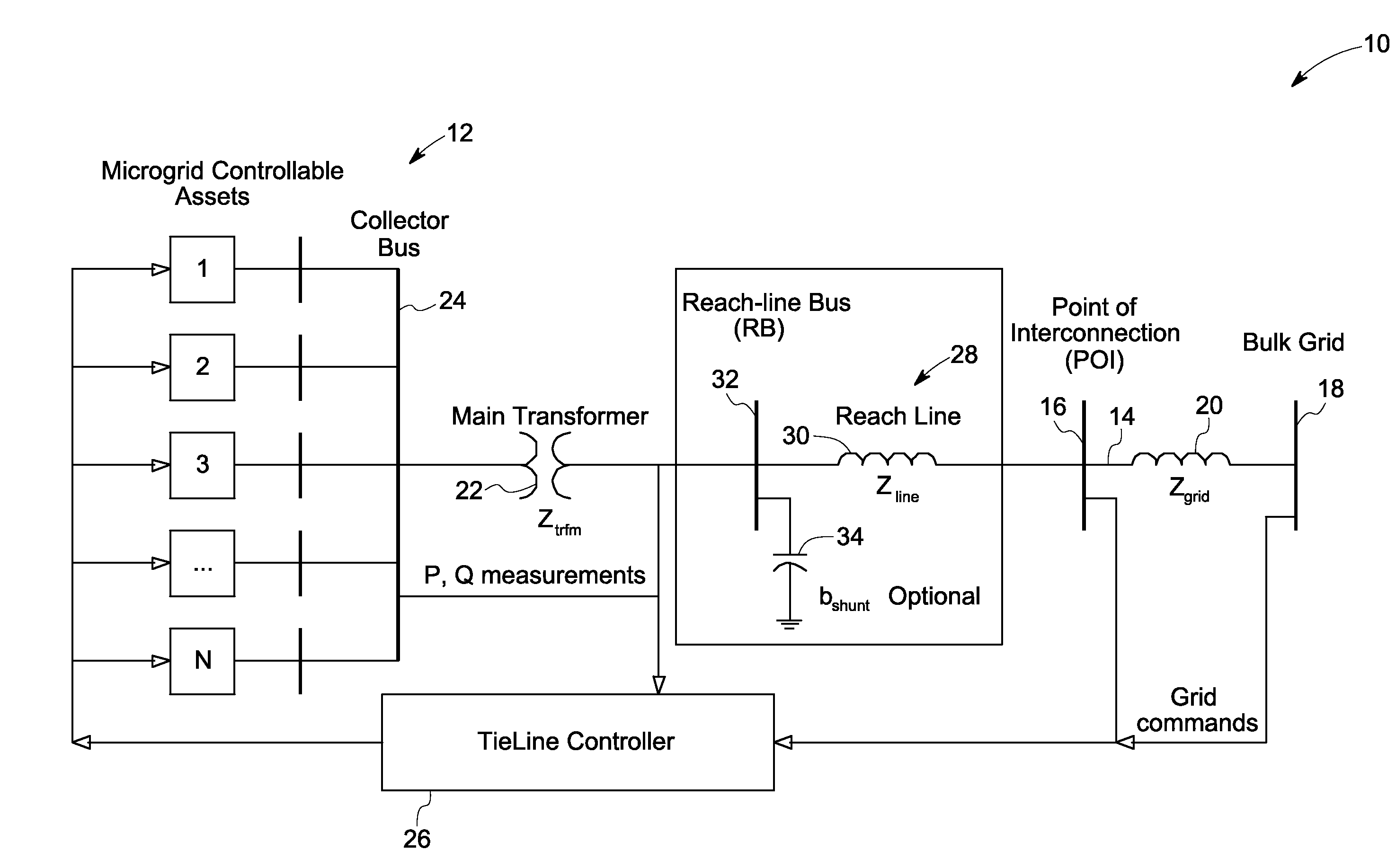
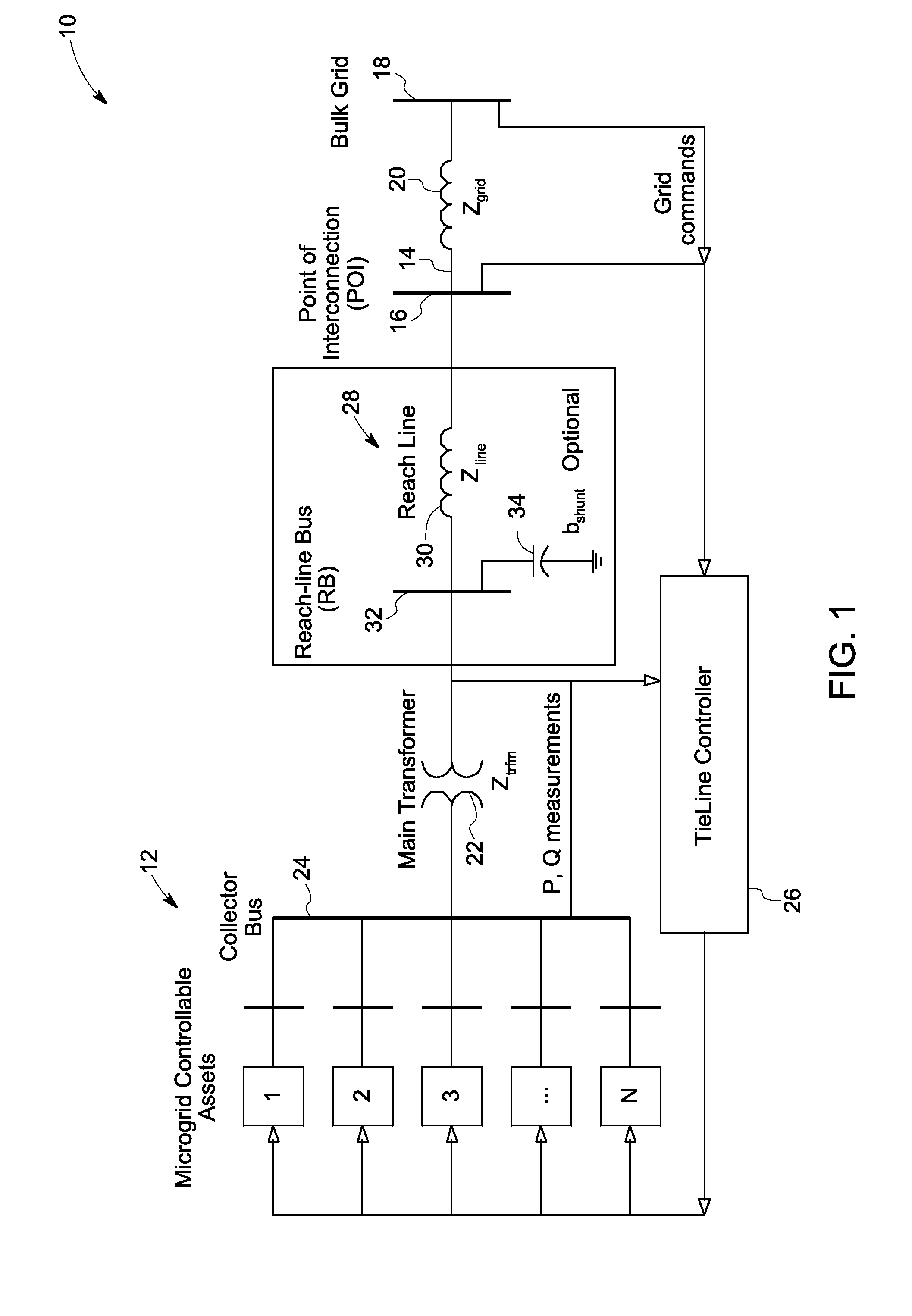
[0017]By controlling the active and reactive power flow through (in and out) a tieline between a microgrid and a bulk grid, the microgrid may both meet point of interconnect (POI) voltage and frequency requirements of the bulk grid and behave as a dispatchable entity to the bulk grid. The system and method described herein enable implementation of the tieline control. The tieline controller described herein may include a flexible design to operate either (1) when the interface power demand is received from the grid operator or (2) as a response to the system conditions such as addition of loads, loss of loads, addition of generation, loss of generation, and degradation of the bulk grid.

[0018]FIG. 1 illustrates a system 10 for controlling a microgrid 12. The system 10 includes different types or same types of microgrid assets (shown generally by reference numbers 1, 2, 3, . . . N). As used herein “different types” is meant to encompass different categories assets (such as, for renewa...


PUM


Abstract

A system for controlling a microgrid includes microgrid assets and a tieline for coupling the microgrid to a bulk grid; and a tieline controller coupled to the tieline. At least one of the microgrid assets comprises a different type of asset than another one of the microgrid assets. The tieline controller is configured for providing tieline control signals to adjust active and reactive power in respective microgrid assets in response to commands from the bulk grid operating entity, microgrid system conditions, bulk grid conditions, or combinations thereof.

Description

STATEMENT REGARDING FEDERALLY SPONSORED RESEARCH & DEVELOPMENT[0001]This invention was made with Government support under contract number DE-FC02-05CH11349 awarded by the Department of Energy. The Government has certain rights in the invention.BACKGROUND[0002]The invention relates generally to microgrids and more particularly to a system and method for controlling microgrids.[0003]A microgrid is defined generally as an aggregation of controllable and uncontrollable assets which may comprise electrical generators, loads, and storage devices, for example. Electrical generators in a microgrid typically include non-conventional energy sources such as micro turbines, wind turbines, photovoltaic systems, fuel cells, or hydrogen fed reciprocating engines, for example. Microgrids may supply power to shopping centers, industrial parks, college campuses or villages, for example.[0004]In order to interconnect a microgrid to a bulk (or main) grid, a utility company will often require the microg...

Claims


Application Information

Patent Timeline
Patent Type & Authority Applications(United States)
IPC IPC(8): G05F1/70
CPCH02J3/06H02J3/08H02J3/383H02J3/382Y02E10/563Y02E10/763H02J3/386Y02P80/14H02J2300/40H02J2300/28H02J2300/20H02J2300/24H02J3/381Y02E10/56Y02E10/76Y02P80/15
Inventor BOSE, SUMITACHILLES, ALFREDO SEBASTIANLIU, YANAHMED, EMAD EZZATGARCES, LUIS JOSE
Owner GENERAL ELECTRIC CO
Why Eureka
Try Eureka