
Respiration Monitoring Apparatus, Respiration Monitoring System, Medical Processing System, Respiration Monitoring Method, And Respiration Monitoring Program

a technology of respiration monitoring and monitoring apparatus, applied in the field of respiration, can solve problems such as giving the subject discomfort or entering the view field, and achieve the effects of increasing or decreasing the area, and reducing the illumination

Inactive Publication Date: 2008-06-19
KK TOSHIBA +1
View PDF3 Cites 11 Cited by
  • Summary
  • Abstract
  • Description
  • Claims
  • Application Information

AI Technical Summary

Benefits of technology

[0036]A respiration monitoring program according to this invention enables a computer to perform: an image-acquiring step that acquires images at predetermined timings by photographing, sideways with respect to a subject, a region-of-interest including at least one of the subject's chest and abdomen and a boundary between at least one of the chest and abdomen and a background having lower illuminance than at least one of the chest and abdomen; and an expiration / aspiration discriminating step that discriminates between the subject's expiration and aspiration, on the basis of a plurality of images acquired at the predetermined timings in the image-acquiring step and in accordance with whether a part of the region-of-interest, which is composed of pixels having luminance higher than a prescribed value, increases or decreases in area.
[0037]Preferably, the respiration monitoring program configured as described above may be so described that, in the expiration / aspiration discriminating step, the subject is determined to be inhaling when that part of the region-of-interest, which is composed of pixels having luminance higher than a prescribed value, increases in area, and the subject is determined to be exhaling when that part of the region-of-interest, which is composed of pixels having luminance higher than a prescribed value, decreases in area.

Problems solved by technology

The device thus attached to the subject may give the subject discomfort or may come into the view field of the imaging apparatus.

Method used


Image

  • Respiration Monitoring Apparatus, Respiration Monitoring System, Medical Processing System, Respiration Monitoring Method, And Respiration Monitoring Program
  • Respiration Monitoring Apparatus, Respiration Monitoring System, Medical Processing System, Respiration Monitoring Method, And Respiration Monitoring Program
  • Respiration Monitoring Apparatus, Respiration Monitoring System, Medical Processing System, Respiration Monitoring Method, And Respiration Monitoring Program

Examples


first embodiment

[0053]The first embodiment of this invention will be described, with reference to the accompanying drawings.

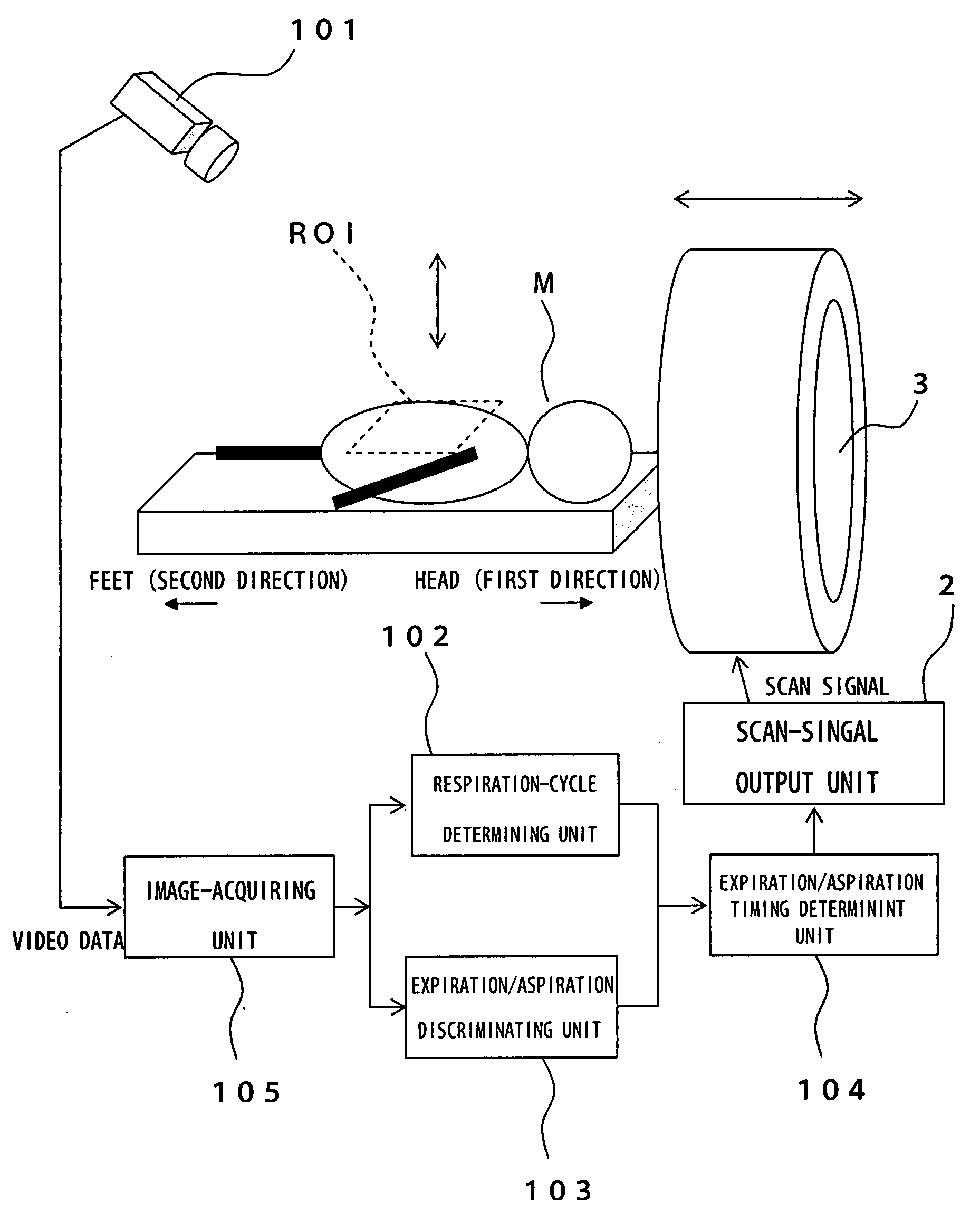
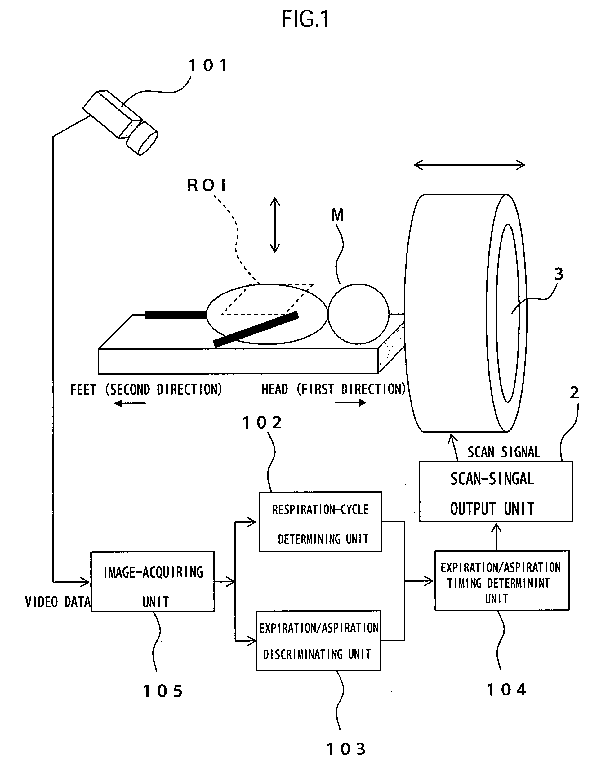
[0054]FIG. 1 is a function block diagram explaining a respiration monitoring apparatus, a respiration monitoring system and a medical processing system, all according to the present embodiment.

[0055]The respiration monitoring apparatus according to the present embodiment comprises a respiration-cycle determining unit 102, an expiration / aspiration discriminating unit 103, an expiration / aspiration timing determining unit 104, an image-acquiring unit 105, a storage unit (not shown), a control unit (not shown), a display unit (not shown), and a notification unit (not shown). The control unit is composed of a CPU, an image-processing circuit (image-processing chip), and the like. The medical processing system according to this embodiment comprises, in addition to the respiration monitoring apparatus, a scan-signal output unit (equivalent to a medical-process executing unit) 2, and ...

second embodiment

[0101]The second embodiment of the present invention will be described.

[0102]This embodiment is a modification of the first embodiment. Therefore, the components identical with those of the first embodiment are designated by the same reference numbers and will not be described. The present embodiment differs from the first embodiment in that the expiration / aspiration discriminating unit 103 determines, by a different method, the direction the pixel moves in the image photographed by the imaging unit 101.

[0103]FIGS. 6 and 7 are flowcharts explaining a method of determining how a pixel moves in the image, by using the expiration / aspiration discriminating unit in the present embodiment. Note that a single flowchart has been divided into FIGS. 6 and 7, for the sake of convenience. FIG. 8 is a diagram showing the motion of a specific block and explaining a method of matching the block. This figure shows that at the timing of the current frame (b), block B in the immediately preceding fra...

third embodiment

[0138]The third embodiment of the present invention will be described below.

[0139]This embodiment is a modification of the first embodiment. Therefore, the components identical with those of the first embodiment are designated by the same reference numbers and will not be described. The present embodiment differs from the first embodiment in that the expiration / aspiration discriminating unit determines, by a different method, discriminate between expiration and aspiration.

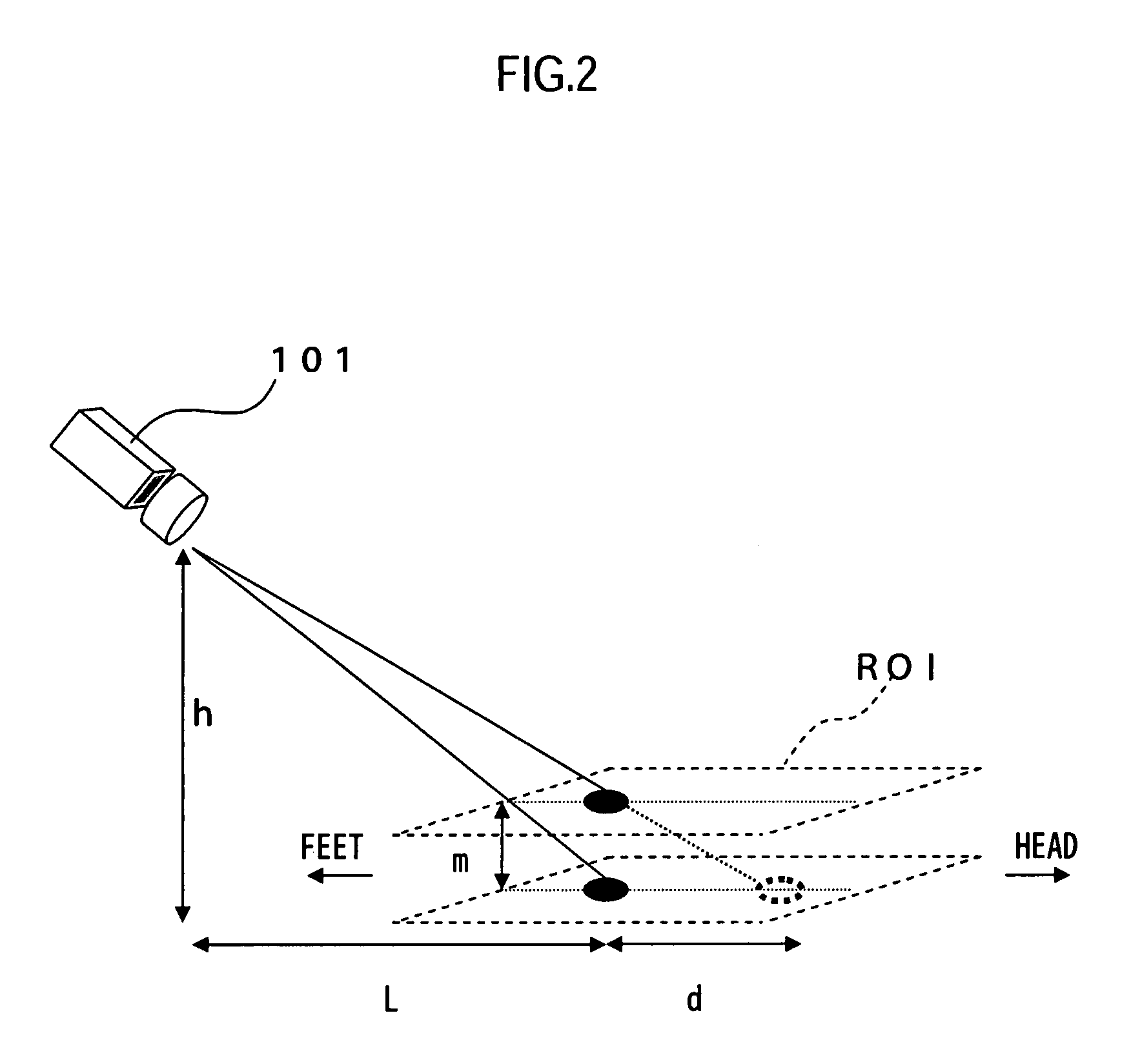
[0140]In the first embodiment, the imaging unit 101 is arranged, inclining to the region-of-interest ROI, which exists in the subject (see FIGS. 1 and 2). In the present embodiment, as shown in FIGS. 9 and 10, the imaging unit 101 is arranged to photograph the region-of-interest ROI, which includes the chest or abdomen of the subject M, or both, sideways with respect to the subject M. The region-of-interest ROI also includes the boundary between the chest or abdomen of the subject M, or both, and the background S. ...


PUM


Abstract

A respiration monitoring apparatus comprises an image-acquiring unit that acquires images at predetermined timings, each image photographed in a direction inclined at a prescribed angle to a region-of-interest including at least one of a subject' s chest and abdomen; and an expiration / aspiration discriminating unit that determines a direction in which a pixel moves, from a positional change of the pixel in an image, on the basis of a plurality of images acquired at consecutive timings by the image-acquiring unit, and discriminates between the subject's expiration and aspiration on the basis of the direction determined.

Description

TECHNICAL FIELD [0001]The present invention relates to a respiration monitoring process for discriminating between the subject's expiration and aspiration.BACKGROUND ART [0002]Hitherto, a technique called respiration-synchronized scan is utilized in imaging processes such as CT scan. This scan is a technique of scanning organs that move as the subject breathes (e.g., lungs, liver, spleens, or the like), at a certain phase of the respiration cycle, thereby to obtain images of the organs.[0003]This technique helps to provide clear images of any organ susceptible to motion artifact due to respiration, not influenced so much by the motion artifact.[0004]In the conventional respiration-synchronized scan, a device is attached to the subject in most cases, which can detect a tension resulting from the respiration, thereby to discriminate between expiration and aspiration. (The device is attached to, for example, a part near the chest or the abdomen.)[0005]The device is attached directly to...

Claims


Application Information

Patent Timeline
Patent Type & Authority Applications(United States)
IPC IPC(8): A61B5/08A61B5/05
CPCA61B5/055A61B6/032A61B5/416A61B5/08A61B6/03G06T7/20
Inventor MIYAKE, YOSHIO
Owner KK TOSHIBA
Learn More