Multiple Drug Injection Apparatus

Inactive Publication Date: 2008-06-19
LAFFERTY JOHN PETER
View PDF10 Cites 12 Cited by
  • Summary
  • Abstract
  • Description
  • Claims
  • Application Information

AI Technical Summary

Benefits of technology

[0011]It is therefore one of the main objects of the present invention to provide a device that contains fluid that can be dispensed quickly.
[0019]It is yet another object of this invention to provide such a device that is inexpensive to manufacture and maintain while retaining its effectiveness.

Problems solved by technology

None of them, however, includes a means to selectively and simply dispense any of several fluids from a single device.

Method used


Image

  • Multiple Drug Injection Apparatus
  • Multiple Drug Injection Apparatus
  • Multiple Drug Injection Apparatus

Examples


Embodiment Construction

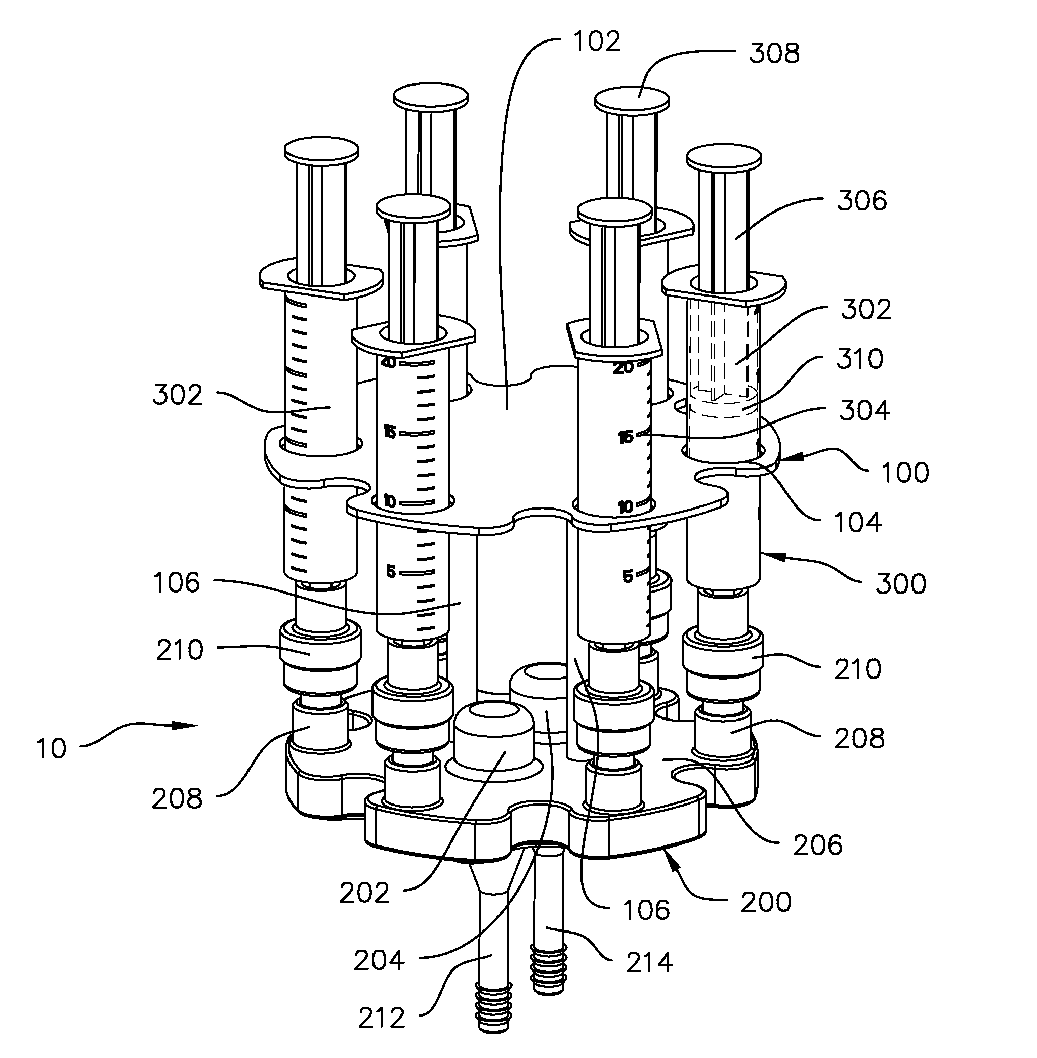
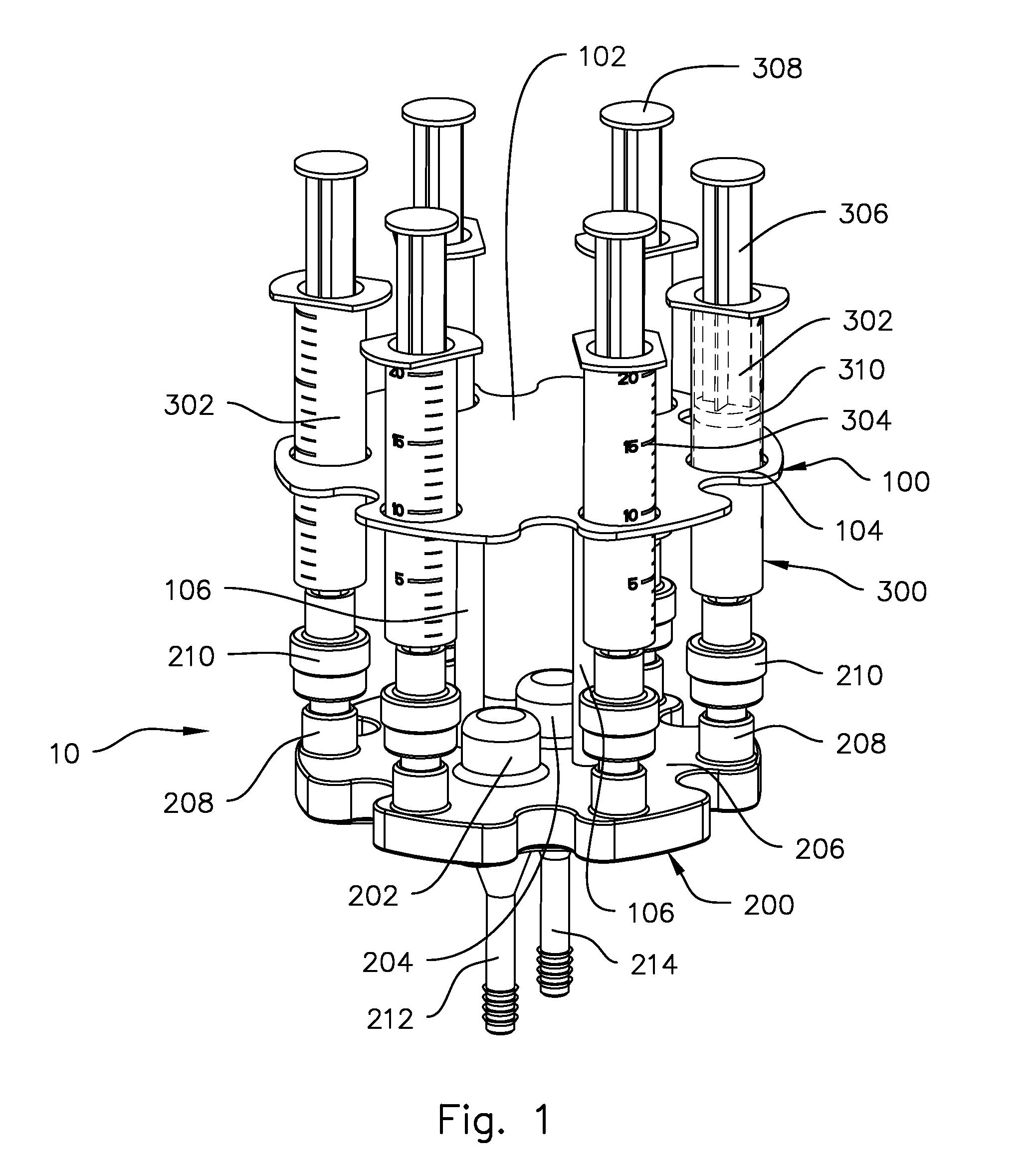
[0025]Referring now to the drawings, where the present invention is generally referred to with numeral 10, it can be observed in FIG. 1 that in this embodiment it basically includes a frame assembly 100, a manifold assembly 200 and a vessel assembly 300.

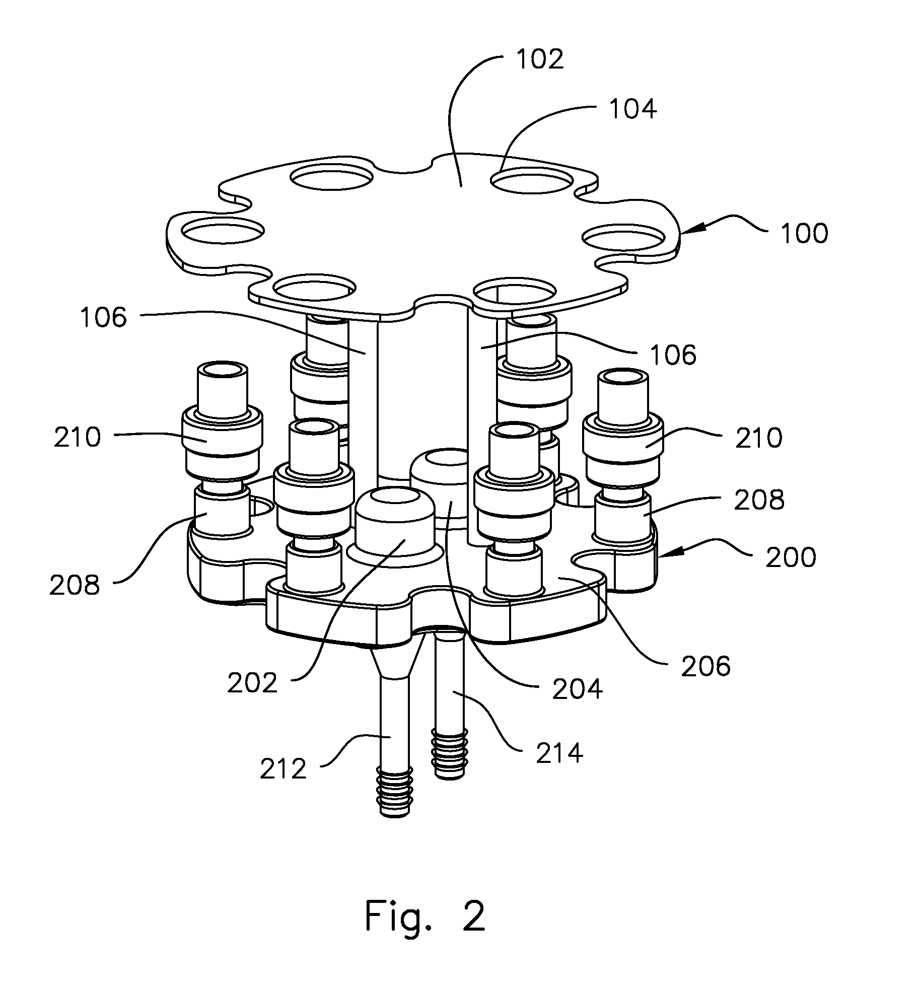
[0026]The frame assembly 100 comprises, inter alia, a plate 102, multiple bores 104 and one or more posts 106. In the preferred embodiment said posts 106 intersect at a substantially right angle and are rigidly affixed to the plate 102. Said plate 102 has a series of bores 104 that are dimensioned to permit a vessel assembly 300 to pass through easily but small enough to prevent the vessel assembly 300 from excessive lateral movement inside the bore 104.

[0027]The vessel assembly 300 comprises, inter alia, a vessel 302, a head 308, a shaft 306 and piston 310. In the preferred embodiment the vessel 302 is a common hypodermic syringe with graduations 304 to indicate the volume of fluid contained inside the vessel 302. In one method of u...


PUM


Abstract

The present invention is a fluid dispensing device particularly suited to medicine but also having many other applications. The user manually and selectively dispenses any of one or more fluids, typically a drug, contained within the device. Generally, the device comprises a frame that holds multiple hypodermic syringes and channels the dispensed fluids through a manifold. A flushing solution, for example a saline solution, enters the manifold, flows past each of the points where the syringes input into the manifold and continues to flow out of the device to a patient where the flushing solution and dispensed fluid are delivered to a patient.

Description

OTHER RELATED APPLICATIONS[0001]The present application is a continuation-in-part pending of U.S. patent application Ser. No. 11 / 610,930, filed on Dec. 14, 2006, which is hereby incorporated by reference.BACKGROUND OF THE INVENTION[0002]1. Field of the Invention[0003]The present invention relates to fluid dispensers, and more particularly, to a fluid dispenser that in the preferred embodiment is suited to dispense drugs.[0004]2. Description of the Related Art[0005]Several designs for fluid dispensers have been designed in the past. None of them, however, includes a means to selectively and simply dispense any of several fluids from a single device.[0006]Applicant believes that the closest reference corresponds to U.S. patent application Ser. No. 11 / 156,575 by inventor Wesley Verkaart. However, it differs from the present invention because the Verkaart invention does not provide a means to precisely dispense liquids, does not provide a means to reduce mixing of the dispensed fluids, ...

Claims


Application Information

Patent Timeline
IPC IPC(8): A61M5/00B67D7/08B67D7/70
CPCA61M5/001A61M2205/8206A61M5/1456A61M5/16827A61M5/19A61M5/2053A61M5/2455A61M5/315A61M5/31591A61M5/46A61M2005/3125A61M2005/3139A61M2005/31508A61M2205/3569A61M2205/502A61M2205/6045A61M5/14526
Inventor LAFFERTY, JOHN PETER
Owner LAFFERTY JOHN PETER
Why Eureka
Try Eureka