Safety detection method for ultrasonic treatment device

a treatment device and detection method technology, applied in the field of safe detection of ultrasonic treatment devices, can solve the problems of many dangers and risks of using ultrasonic treatment devices, inability to use the device at a fixed position, and inability to safely and effectively use ultrasonic treatment devices

Inactive Publication Date: 2011-06-02
LIN HSIN YI
View PDF2 Cites 3 Cited by
  • Summary
  • Abstract
  • Description
  • Claims
  • Application Information

AI Technical Summary

Benefits of technology

[0009]The techniques employed by the present invention can determine whether or not the probe of the ultrasonic treatment device is in motion or sliding according to set parameters during use, whether or not it is staying at a point unmoving for a long period of time, or if it is not in contact with the surface of the skin causing a zero load to happen. The moment it is determined that any of the above is at risk to the user or will cause injuries, the ultrasonic energy is stopped or paused from being emitted to prevent the user from injuries or danger during use of the device. Therefore, the user is able to safely and effectively use the ultrasonic treatment device.

Problems solved by technology

In accordance with the foregoing, there are many dangers and risks when using an ultrasonic treatment device.
The biggest problem is being unable to use the device at a fixed point for a long period of time.
If left in contact in the same position for a long period of time, the wave energy accumulated would cause subcutaneous tissue or organs to be injured.
Furthermore, when the energy of the ultrasonic treatment device is under a no-load condition (zero load), the energy in the probe is unable to dissipate, resulting in the heating up of the probe which could very easily cause burns when a user is not paying attention.

Method used


Image

  • Safety detection method for ultrasonic treatment device
  • Safety detection method for ultrasonic treatment device
  • Safety detection method for ultrasonic treatment device

Examples


Embodiment Construction

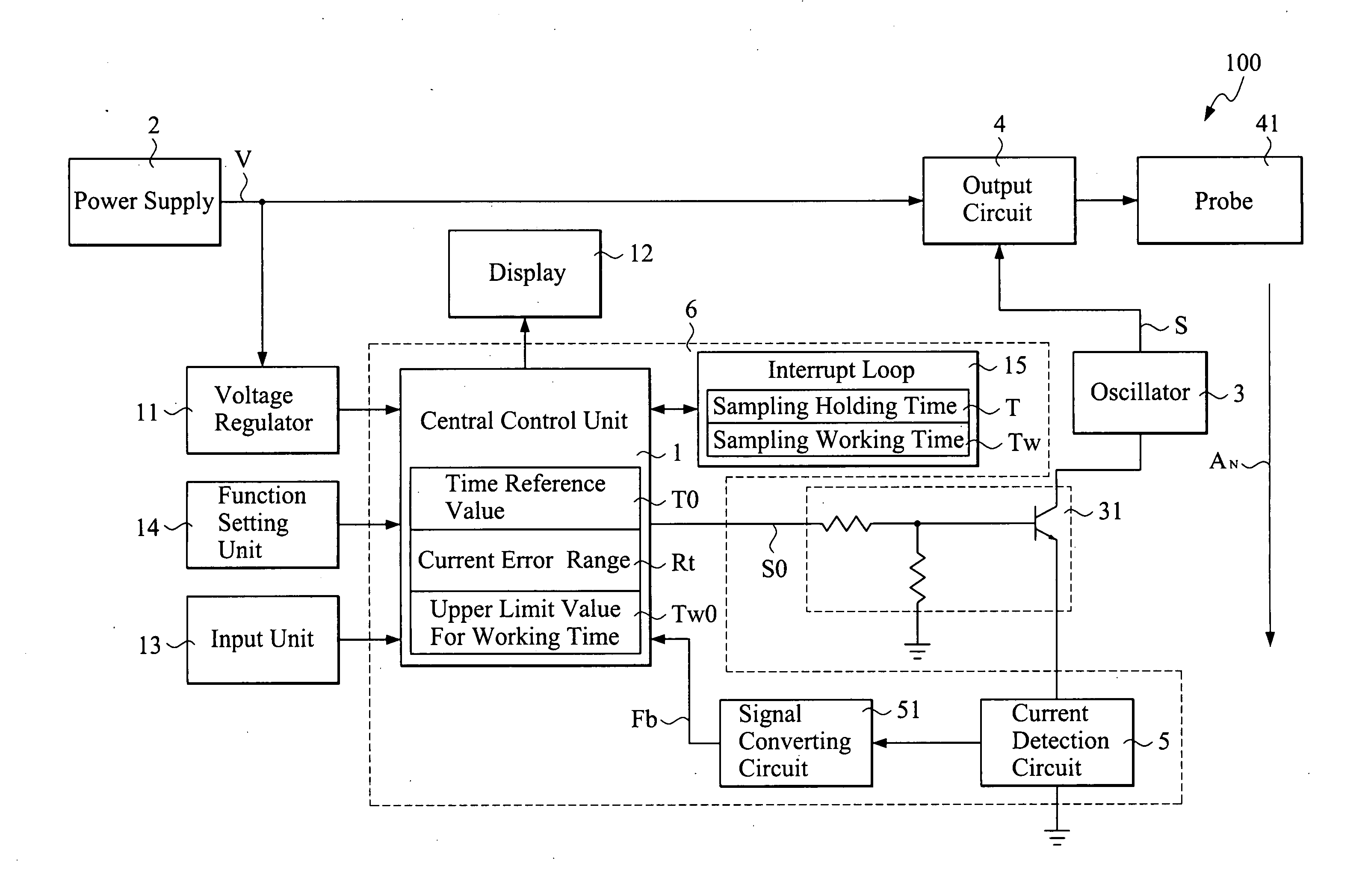
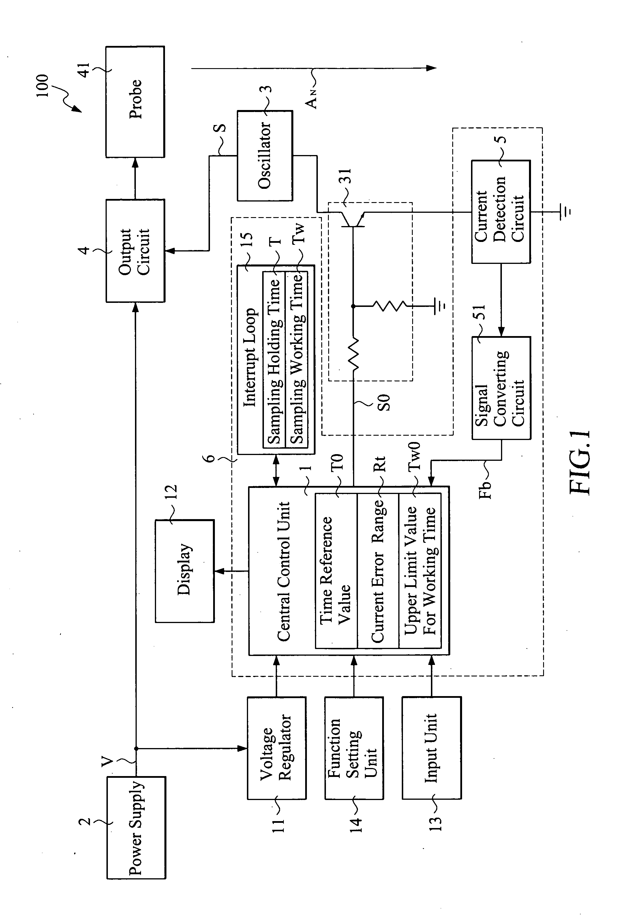
[0013]FIG. 1 illustrates a control circuit of an ultrasonic treatment device 100. The ultrasonic treatment device 100 comprises a central control unit 1, a power supply 2, an oscillator 3, an output circuit 4, and a current detection circuit 5.

[0014]The central control unit 1 controls the entire ultrasonic treatment device and is connected to a voltage regulator 11, a display 12, an input unit 13, a function setting unit 14, and an interrupt loop 15. The voltage regulator H is connected to the power supply 2 to regulate an input power source V provided by the power supply 2, and then supply the input power source V to the central control unit 1. The display 12 provides the function for displaying images, graphics, data, information, etc. The input unit 13 provides input commands. The function setting unit 14 enables the setting of high / low mode, the timer, and the memory for emitting the ultrasonic energy. The interrupt loop 15 provides various interrupt timing.

[0015]The oscillator ...


PUM


Abstract

A detection method for an ultrasonic treatment device is disclosed. A current value presently flowing through an output circuit of the ultrasonic treatment device is detected when a probe of the ultrasonic treatment device is in contact with a surface of a user's skin. Whether or not the change in the current values maintains within a predetermined current error range is determined, and whether or not a sampling holding time during which the change in the current values maintains within the current error range exceeds a predetermined time reference value is also determined. When the probe is determined to be under abnormal conditions according to the current error range, time reference value and the upper limit value of working time, the probe is stopped from generating ultrasonic energy, thereby lowering the risks for the user and preventing the user from injuries.

Description

FIELD OF THE INVENTION[0001]This invention relates to the design for safely using an ultrasonic treatment device, and particularly to a detection method for an ultrasonic treatment device.BACKGROUND OF THE INVENTION[0002]Conventional heat therapy for treatments of bone, muscle and other sports injuries is nothing more than covering injuries with a hot towel, steaming, or directly soaking the injured parts in hot water. However, these methods can only conduct the heat to the surface of the skin, thus is unable to conduct the heat deeply into the muscle and bone, particularly to treat maladies of the joints and deep seated muscles.[0003]Therefore, the industry has developed an ultrasonic treatment device that uses the resonance principles of ultrasonic waves to transfer heat into the bones and muscles. The ultrasonic wave is transferred to the injured bones, muscles or joints to enhance the metabolism of the bodies that can reduce and alleviate the pains and cure the parts. Moreover, ...

Claims


Application Information

Patent Timeline
Patent Type & Authority Applications(United States)
IPC IPC(8): A61N7/00
CPCA61N7/00A61B2019/465A61B2090/065
Inventor LIN, HSIN-YI
Owner LIN HSIN YI
Why Eureka
Try Eureka