
System and method for controlling horsepower in a locomotive consist

a technology of control system and consists, which is applied in the direction of position/direction control, locomotives, instruments, etc., can solve the problems of coarseness of horsepower control, increase in horsepower per notch setting, and increase in horsepower per uni

Inactive Publication Date: 2008-06-19
ZTR CONTROL SYST INC
View PDF5 Cites 37 Cited by
  • Summary
  • Abstract
  • Description
  • Claims
  • Application Information

AI Technical Summary

Benefits of technology

[0008]In one aspect, there is provided, a method for controlling horsepower output in a consist of at least two locomotives comprising receiving an input indicative of a requested incremental change in horsepower; determining a current horsepower output for the consist and a current notch combination for the at least two locomotives generating the current horsepower; determining a next notch combination for the at least two locomotives in the direction of the incremental change having associated therewith, an expected horsepower output; determining a target horsepower output which is between the expected horsepower output and the current horsepower output according to the incremental change; referencing a set of one or more transitional horsepower outputs at alternative notch combinations and determining a desired one of the alternative notch combinations having a corresponding transitional horsepower output which is within a predetermined range of the target horsepower; and adjusting throttle notch positions in each the at least two locomotives according to the desired one of the alternative notch combinations.
[0009]In another aspect, there is provided a computer readable medium comprising computer executable instructions thereon for causing a processor in a control system to perform the above method.
[0010]In yet another aspect, there is provi

Problems solved by technology

One disadvantage of higher output locomotives is that, in order to comply with existing interchange standards, the horsepower is controlled using eight throttle or “notch” positions and, therefore, the incremental increase in horsepower per notch setting becomes greater as horsepower per unit increases.
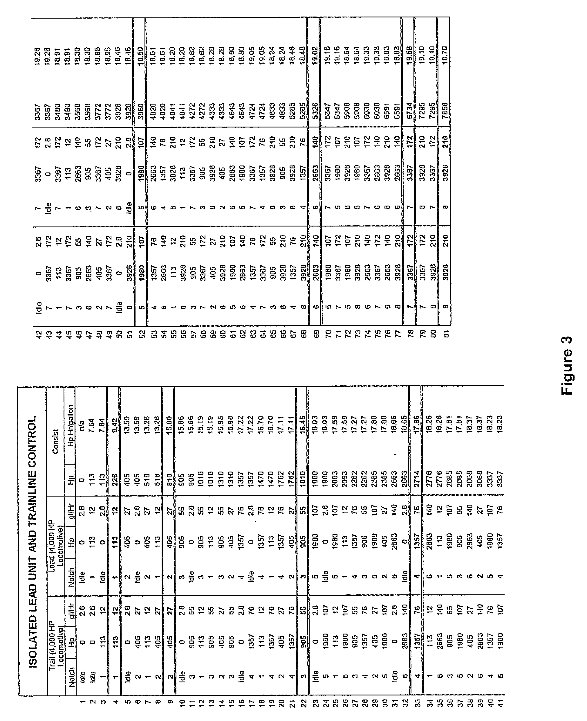
However, it can be seen that as more and more locomotives are combined in a consist, the coarseness of the horsepower control becomes more evident.

Method used


Image

  • System and method for controlling horsepower in a locomotive consist
  • System and method for controlling horsepower in a locomotive consist
  • System and method for controlling horsepower in a locomotive consist

Examples


Embodiment Construction

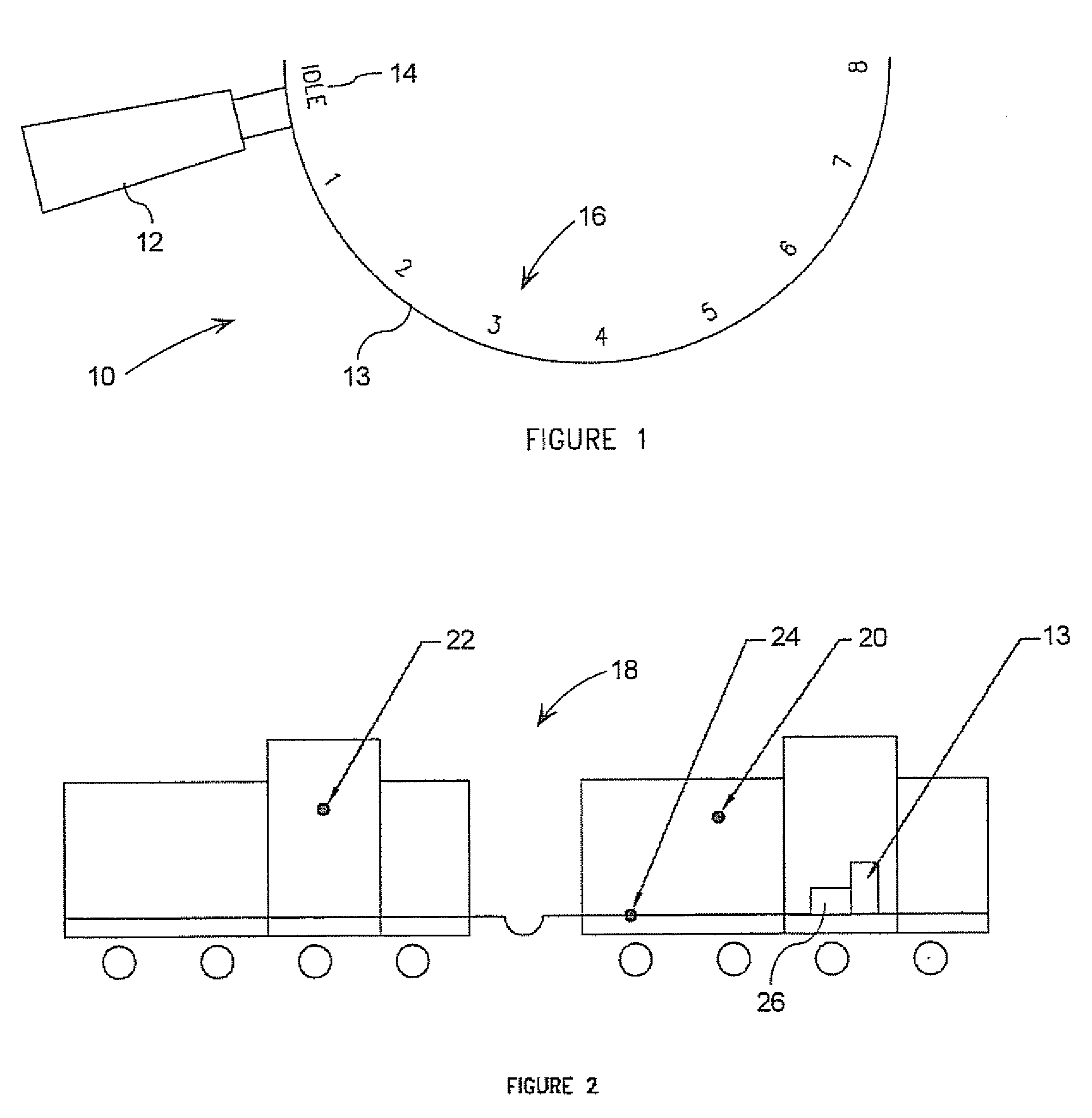
[0019]Referring to FIG. 1, a throttle controller 10 for a locomotive (not shown) comprises a throttle handle 12 supported by a control stand 11, an idle position 14, and eight throttle settings 16 provided by the control stand 13. The throttle settings may also be referred to herein as notch 1, notch 2, etc. Typically, there is a spring loaded cam (not shown) integrated with the throttle handle 12 that positions the throttle handle 12 securely into physical notches in the control stand 13, hence the term “notch”. As such, it will be appreciated that the terms “throttle position” and “notch position” are interchangeable.

[0020]When the throttle handle 12 is placed in the idle position 14, no tractive effort is generated by the locomotive. Notch 8 provides the maximum horsepower output for the locomotive. Notch 1 through notch 7 are interval steps in horsepower between zero (0) and maximum horsepower achieved by selecting notch 8.

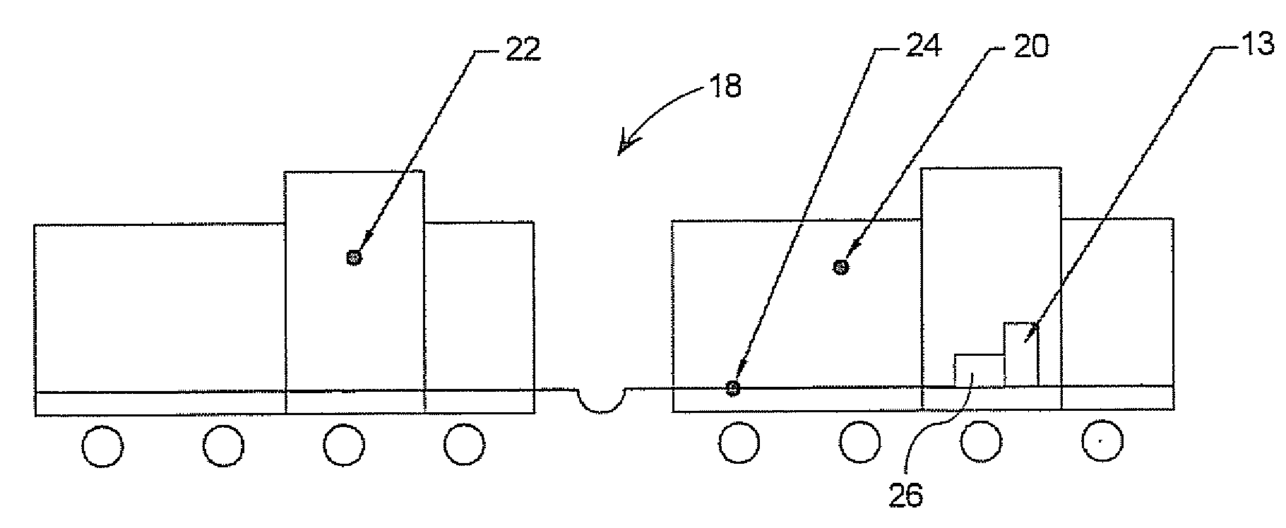
[0021]FIG. 2 illustrates a two-unit locomotive consist 1...


PUM


Abstract

A consist controller is provided that enables an operator to take advantage of all horsepower combinations for locomotives in a consist. The consist controller provides a fractional increase option and a fractional decrease option that enables the operator to increase or decrease horsepower output with finer adjustments. In a preferred implementation, the fractional increases and decreases are used in conjunction with a fuel optimization routine such that the target setpoint, from which a range of horsepower values is computed, can be increased or decreased in steps that are less than a full notch increase or decrease.

Description

[0001]This application claims priority from U.S. Provisional Application No. 60 / 870,506 filed on Dec. 18, 2006, the contents of which are incorporated herein by reference.FIELD OF THE INVENTION[0002]The present invention relates to control systems for locomotive consists and has particular utility in controlling horsepower in such consists.DESCRIPTION OF THE PRIOR ART[0003]The horsepower output of freight locomotives has increased in recent history, often producing in the range of 4000-6000 Hp. The advantages of a higher output are many and well known, including the ability to carry a similar load with fewer locomotives, and a higher fuel efficiency. One disadvantage of higher output locomotives is that, in order to comply with existing interchange standards, the horsepower is controlled using eight throttle or “notch” positions and, therefore, the incremental increase in horsepower per notch setting becomes greater as horsepower per unit increases. Table 1 below illustrates approxi...

Claims


Application Information

Patent Timeline
IPC IPC(8): F02D28/00
CPCF02D29/06
Inventor LIBERATORE, ALDO
Owner ZTR CONTROL SYST INC
Learn More