Apparatus and method for monitoring and debugging query execution objects

a technology of query execution and apparatus, applied in the field of computer systems, can solve the problems of complex data structure of complicated queries, difficulty in debugging queries of this complexity, and typical set breakpoints, and achieve the effect of efficient monitoring and debugging

Active Publication Date: 2008-06-19
IBM CORP
View PDF18 Cites 3 Cited by
  • Summary
  • Abstract
  • Description
  • Claims
  • Application Information

AI Technical Summary

Benefits of technology

[0011]According to the preferred embodiments, nodes in a query execution data structure have monitor and dump methods defined. The monitor method enables the collection of information from the node. The dump method outputs the monitored information from each node. A monitor and debug mechanism of the preferred embodiments includes a graphical user interface that allows a user to graphically examine a query execution tree, to enable monitoring of the nodes on a node-by-node basis, and to view information dumped from the query execution data structure as the query is executed or after the query is executed. The result is a powerful tool that allows efficiently monitoring and debugging a query implemented in an object oriented query execution data structure.

Problems solved by technology

One potential problem with the query execution data structure in U.S. Pat. No. 6,915,291 is the complexity of the data structure for complicated queries.
A query of this complexity becomes very difficult to debug.
The problem with a statement level debugger is that a breakpoint is typically set when a particular object is executed.
Note, however, that a given object type may appear in a query execution data structure at a number of different locations, each executing the same implementation methods, but potentially only one of these objects is actually contributing to the problem being debugged.
The result is a debugger that breaks an excessive number of times.
Current debuggers do not have the capability of executing a query execution object to the point of failure, and halting execution at the proper place and time in the code, even using elaborate debugger macros.
As a result, it is very difficult, if not impossible, to debug a complex query execution data structure that includes many query execution objects using known statement level debuggers.
Without a way to debug query execution data structures, the prior art will continue to suffer from inefficient ways of debugging queries.

Method used


Image

  • Apparatus and method for monitoring and debugging query execution objects
  • Apparatus and method for monitoring and debugging query execution objects
  • Apparatus and method for monitoring and debugging query execution objects

Examples


Embodiment Construction

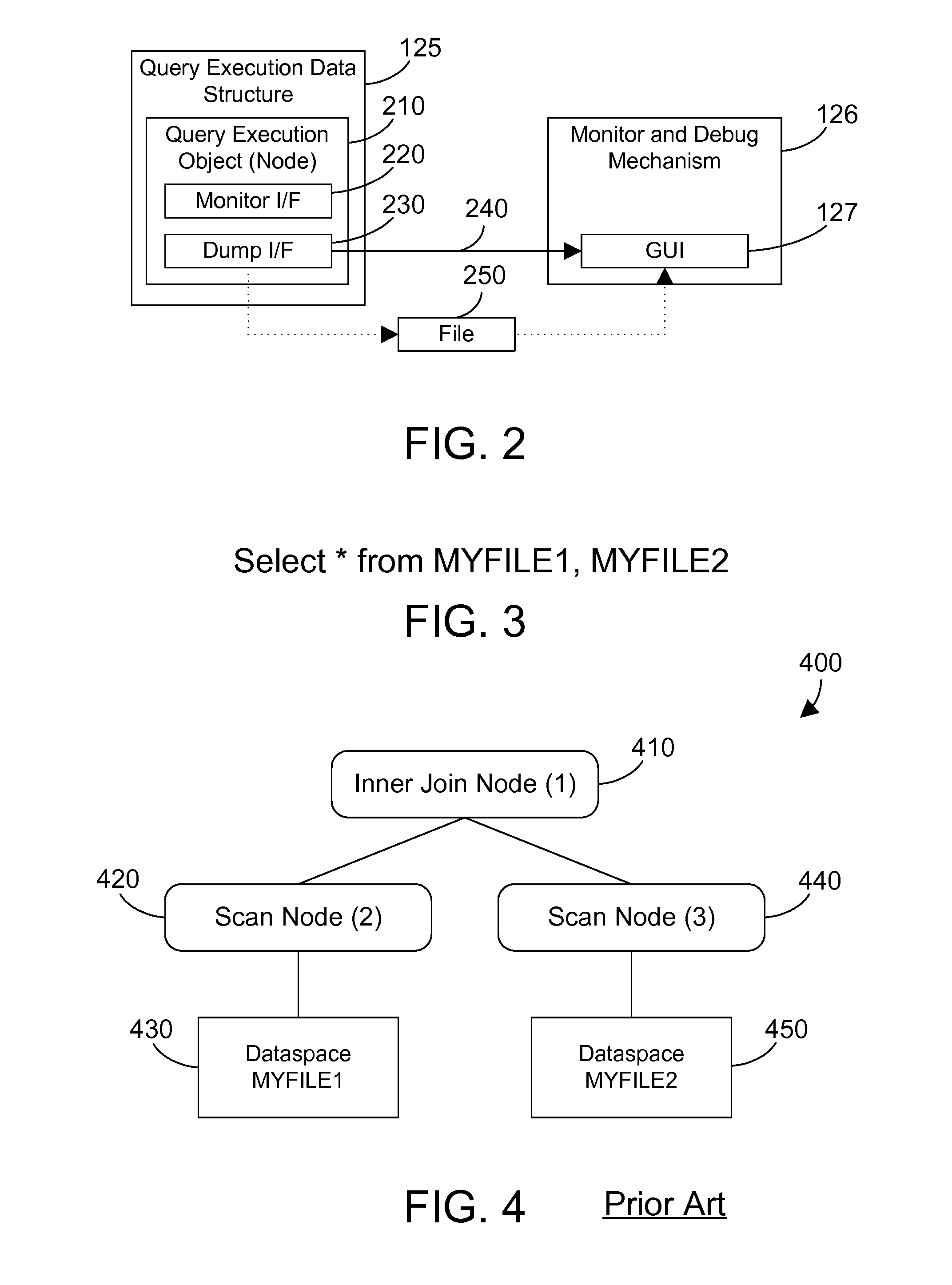
[0029]The preferred embodiments provide an efficient way to monitor a query execution data structure as it executes, which allows for debugging a query corresponding to the query execution data structure. Each node in the query execution data structure includes a monitor( ) method that enables collection of monitored data, and a dump( ) method that outputs the monitored data. A debug and monitor mechanism receives the monitored data, and displays information corresponding to the monitored data in a graphical user interface. The debug and monitor mechanism allows monitoring and debugging a query as the query executes, thereby allowing a powerful tool for real-time monitoring and debugging.

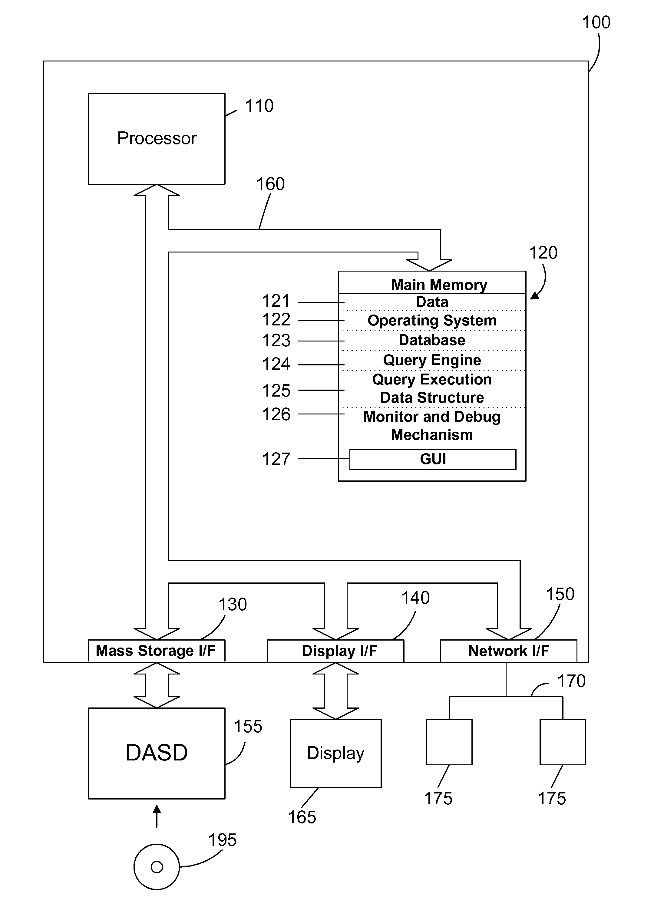
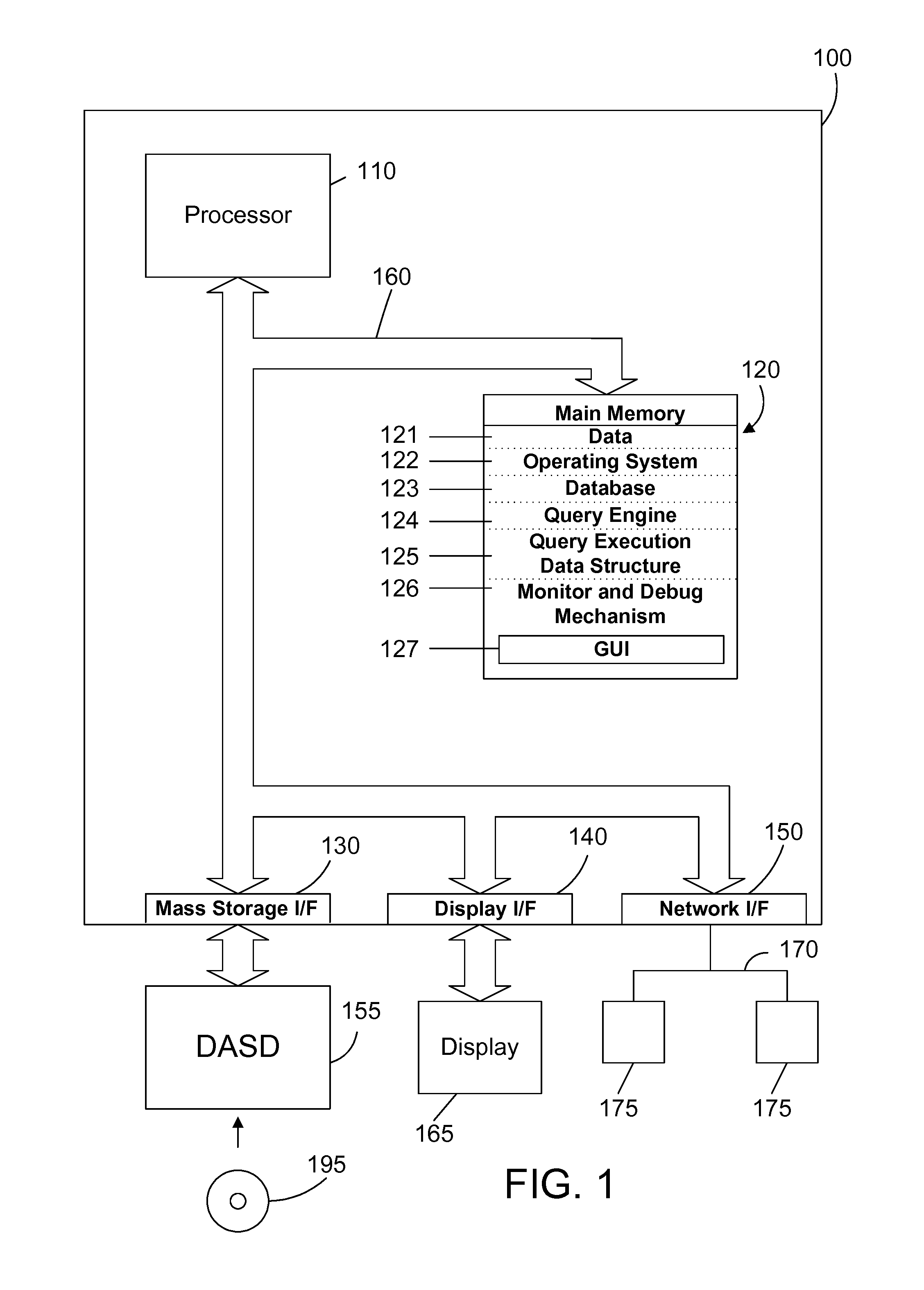
[0030]Referring to FIG. 1, a computer system 100 is one suitable implementation of an apparatus in accordance with the preferred embodiments of the invention. Computer system 100 is an IBM eServer iSeries computer system. However, those skilled in the art will appreciate that the mechanisms and appa...


PUM


Abstract

Nodes in a query execution data structure have monitor and dump methods defined. The monitor method enables the collection of information from the node. The dump method outputs the monitored information from each node. A monitor and debug mechanism of the preferred embodiments includes a graphical user interface that allows a user to graphically examine a query execution tree, to enable monitoring of the nodes on a node-by-node basis, and to view information dumped from the query execution data structure as the query is executed or after the query is executed. The result is a powerful tool that allows efficiently monitoring and debugging a query implemented in an object oriented query execution data structure.

Description

CROSS-REFERENCE TO PARENT APPLICATION[0001]This patent application is a continuation of an application of the same title, U.S. Ser. No. 11 / 282,030, filed on Nov. 12, 2005, which is incorporated herein by reference.BACKGROUND OF THE INVENTION[0002]1. Technical Field[0003]This invention generally relates to computer systems, and more specifically relates to database apparatus and methods.[0004]2. Background Art[0005]Database systems have been developed that allow a computer to store a large amount of information in a way that allows a user to search for and retrieve specific information in the database. For example, an insurance company may have a database that includes all of its policy holders and their current account information, including payment history, premium amount, policy number, policy type, exclusions to coverage, etc. A database system allows the insurance company to retrieve the account information for a single policy holder among the thousands and perhaps millions of p...

Claims


Application Information

Patent Timeline
Patent Type & Authority Applications(United States)
IPC IPC(8): G06F11/32G06F17/30
CPCG06F17/30483G06F3/048G06F17/30289G06F16/21G06F16/24553
Inventor CARLSON, DAVID GLENNHOESCHEN, STEVEN VIRGILKATHMANN, KEVIN JAMES
Owner IBM CORP
Why Eureka
Try Eureka