Turbine and pump shells for torque converters and methods of manufacturing

a technology of torque converters and turbine shells, applied in the direction of fluid gearings, couplings, belts/chains/gearings, etc., can solve the problems of reducing the efficiency of torque converters to 92-93%, misalignment of blades and blade tabs, and reducing the efficiency of peak torque converters. , to achieve the effect of reducing waste, reducing blade tab misalignment and leakage, and improving manufacturability

Active Publication Date: 2008-06-26
SCHAEFFLER TECH AG & CO KG
View PDF5 Cites 6 Cited by
  • Summary
  • Abstract
  • Description
  • Claims
  • Application Information

AI Technical Summary

Benefits of technology

[0028]It is a further objective of the present invention to improve manufacturability and limit waste in the manufacturing of turbine and pump shell and blade assemblies, by reducing blade tab misalignment and leakage during brazing.

Problems solved by technology

At speed ratios less than 1, the torque converter is less than 100% efficient.
Peak torque converter efficiency is limited to 92-93% based on losses in the fluid.
This forming process deforms the slots and can result in misaligned blades and blade tabs.
Thus, the prior art is not able to form a slot shape and width such that their dimensions after the final stamping / forming process are within acceptable tolerance limits to engage with the blades and blade tabs.
Misaligned blade tabs result in poor attachment of a blade to a shell.
Poorly attached blades can easily break away from the shell when the torque converter is in use.
Thus, misaligned structures are usually scrapped.
The position and level of deformation of the slots can lead to brazing paste leaking through the slots and depositing atop the furnace belt.
The deposition of brazing paste leads to delays in factory processes and can result in furnace malfunction.
Because the blade tabs for indents do not structurally hold the blades in place against the shell, it is often difficult and not cost effective to only use indents to arrange a plurality of blades against a shell and braze or weld the blades into place.
However, this process is prone to failure inadequate alignment between blade tabs and indentations.

Method used


Image

  • Turbine and pump shells for torque converters and methods of manufacturing
  • Turbine and pump shells for torque converters and methods of manufacturing
  • Turbine and pump shells for torque converters and methods of manufacturing

Examples


Embodiment Construction

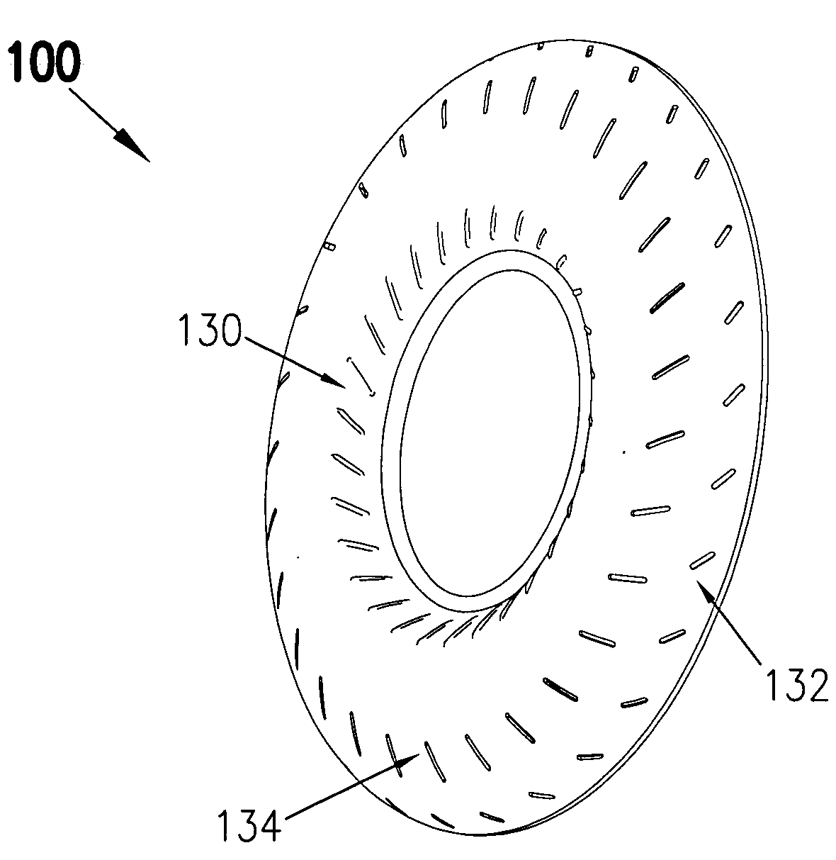
[0047]At the outset, it should be appreciated that like drawing numbers on different drawing views identify identical structural elements of the invention. While the present invention is described with respect to what is presently considered to be the preferred embodiments, it is understood that the invention is not limited to the disclosed embodiments. In the description below, the terms “top”, “bottom”, “upper”, “lower”, “front”, “back”, “rear”, “left”, “right”, and their derivatives, should be interpreted from the perspective of one viewing the invention shown in FIG. 1.

[0048]Furthermore, it is understood that this invention is not limited to the particular methodology, materials and modifications described and as such may, of course, vary. It is also understood that the terminology used herein is for the purpose of describing particular embodiments only, and is not intended to limit the scope of the present invention.

[0049]Unless defined otherwise, all technical and scientific t...


PUM

PropertyMeasurementUnit
semi-toroidal shapeaaaaaaaaaa
torqueaaaaaaaaaa
speedaaaaaaaaaa

Abstract

A blade with first and second blade tabs extending outwardly from an edge of the blade; and a shell with a first indent and a first slot. The first blade tab is arranged to engage the first indent and the second blade tab is arranged to engage the first slot. In one embodiment, the first indent is arranged radially inward on the shell relative to the first slot. In one embodiment, the first blade tab is affixed to the first indent. In one embodiment, the second blade tab is bent over an outside surface of the turbine shell. In one embodiment, the shell includes a second indent and the blade includes a third blade tab extending outwardly from the edge and at least partially disposed in the second indent. A method of manufacturing a pump or turbine shell for a torque converter

Description

CROSS-REFERENCE TO RELATED APPLICATIONS[0001]This application claims the benefit under 35 U.S.C. §119(e) of U.S. Provisional Application No. 60 / 876,215, filed Dec. 21, 2006.FIELD OF THE INVENTION[0002]The invention relates generally to torque converters, and more specifically, to components for torque converters, namely turbine and pump shells having blades attached by means of blade tabs, and to methods of manufacturing.BACKGROUND OF THE INVENTION[0003]FIG. 1 illustrates a general block diagram showing the relationship of the engine 7, torque converter 10, transmission 8, and differential / axle assembly 9 in a typical vehicle. It is well known that a torque converter is used to transmit torque from an engine to a transmission of a motor vehicle.[0004]The three main components of the torque converter are the pump 37, turbine 38, and stator 39. The torque converter becomes a sealed chamber when the pump is welded to cover 11. The cover is connected to flexplate 41 which is, in turn, b...

Claims


Application Information

Patent Timeline
Patent Type & Authority Applications(United States)
IPC IPC(8): F16D33/00B23P15/00F16H41/24
CPCB23P15/006Y10T29/4933F16H41/28F16H41/24
Inventor WOLF, HERBERTBRUCATO, DAVID
Owner SCHAEFFLER TECH AG & CO KG
Why Eureka
Try Eureka