
Cryogenic cooling system with energy regeneration

a cryogenic cooling and energy regeneration technology, applied in the field of cryogenic cooling systems, can solve the problems of consuming energy, generating even more heat, and needing to remove the heat from the device,

Inactive Publication Date: 2008-06-26
SNYTSAR ROMAN
View PDF8 Cites 25 Cited by
  • Summary
  • Abstract
  • Description
  • Claims
  • Application Information

AI Technical Summary

Problems solved by technology

Modern microelectronic devices generate substantial amounts of heat during their operation.
This presents both the problem and the opportunity.
The problem is the need to remove the heat from the device to avoid overheating.
This requires a cooler or heat pump that consumes energy and generates even more heat in the vicinity of the device.
No systems are known to use the cryogenic power cycle for micro-power generation.

Method used


Image

  • Cryogenic cooling system with energy regeneration
  • Cryogenic cooling system with energy regeneration
  • Cryogenic cooling system with energy regeneration

Examples


Embodiment Construction

[0021]I propose a system that uses a vessel with cryogenic liquid for energy storage, cools the microelectronic device with the liquid and generates electric energy by utilizing the heat from the device and from the environment.

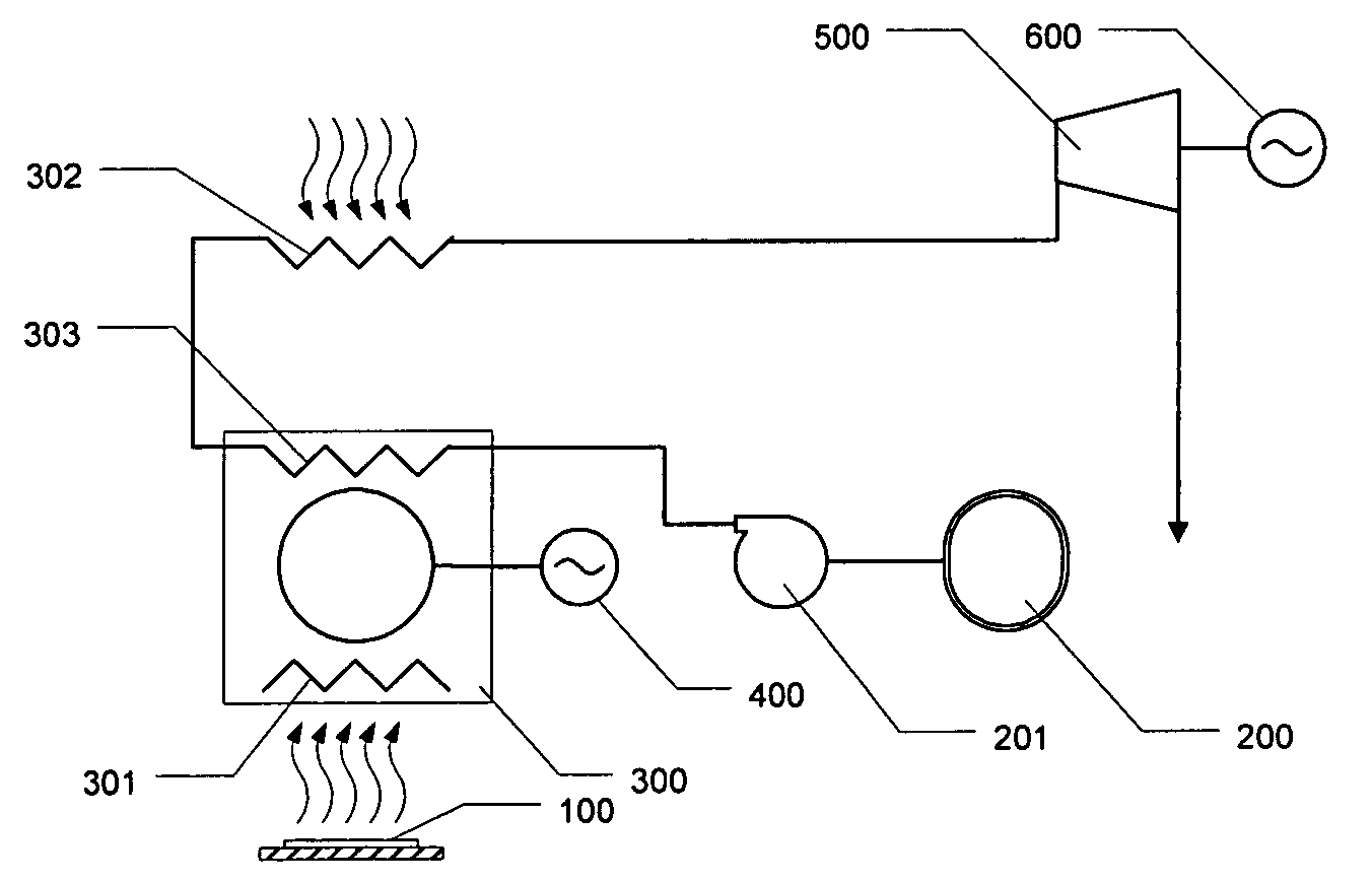
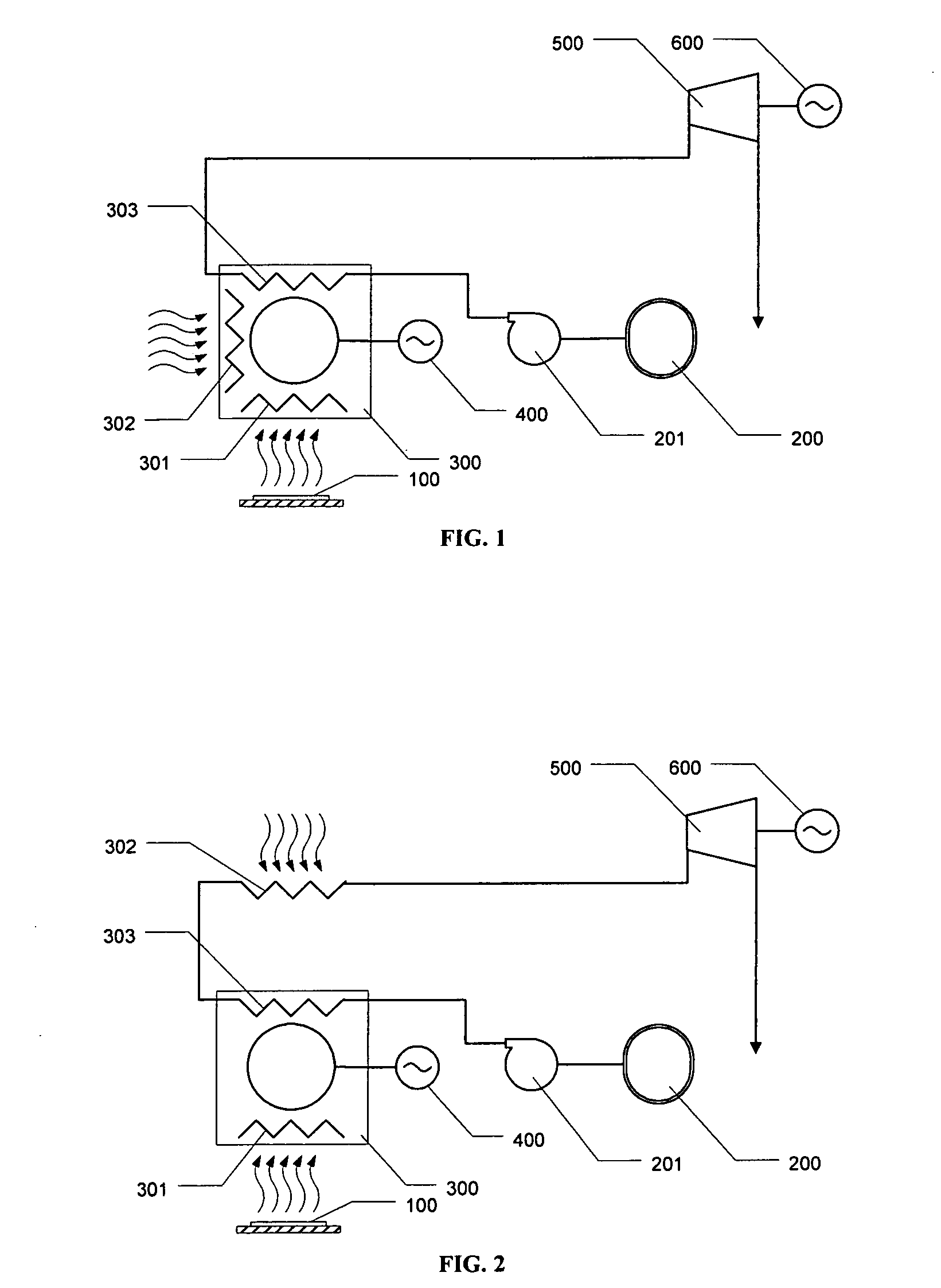
[0022]The main components of the system are shown on FIG. 1. Reversible heat engine (e.g. Stirling cycle engine) 300 is equipped with two “hot” heat exchangers. Heat exchanger 301 absorbs heat from the microelectronic device 100 and heat exchanger 302 absorbs heat from the ambient air. Heat is partially converted into the mechanical energy and then into the electrical energy by the electric generator 400. The residual heat is sunk at the “cold” heat exchanger 303. Pump 201 forces the cryogenic liquid from the heat insulated vessel 200 through the heat exchanger 303. There the liquid evaporates and the vapor is superheated to the ambient air temperature. The vapor is directed into the expander type turbine 500 connected to the electric generator 600.

[0023]Sinc...


PUM


Abstract

The invention provides an efficient way of cooling of the microelectronic devices and converting the heat back into the electrical power. With addition of the ambient-air heat exchanger the system generates enough power to completely satisfy the demand of the microelectronic device and replace the electric battery with the cryogenic storage vessel.

Description

CROSS-REFERENCE TO RELATED APPLICATIONS[0001]NoneFEDERALLY SPONSORED RESEARCH[0002]Not ApplicableSEQUENCE LISTING OR PROGRAM[0003]Not ApplicableBACKGROUND OF THE INVENTION[0004]1. Field of Invention[0005]The present application generally relates to the cooling systems, and in particular, the present invention relates to an electrical energy-generating cooling system and to a cryogenic cooling system.[0006]2. Prior Art[0007]Modern microelectronic devices generate substantial amounts of heat during their operation. This presents both the problem and the opportunity.[0008]The problem is the need to remove the heat from the device to avoid overheating. Usually the heat has to be dissipated into the ambient air with the temperature 20-30K below the temperature of the device. This calls for massive heat exchangers with developed surfaces, pumps or fans for the forced convection. Many attempts have been made to cool the microelectronic device with the media colder than the ambient air. Thi...

Claims


Application Information

Patent Timeline
IPC IPC(8): F25D23/12F25B21/02F25B27/00F02G1/04
CPCF01K25/10F02G1/043F25B2400/141F02G2280/20F25B19/005F02G2254/45
Inventor SNYTSAR, ROMAN
Owner SNYTSAR ROMAN
Learn More