Replacement assembly of handle tool

a technology for replacing parts and tools, applied in the field of hand tools, can solve the problems of increasing the rate of faults, complicated structure of the opener head, and many processes, and achieve the effect of simple structure, easy operation and convenient us

Active Publication Date: 2008-06-26
LAI JIN TSAI
View PDF5 Cites 45 Cited by
  • Summary
  • Abstract
  • Description
  • Claims
  • Application Information

AI Technical Summary

Benefits of technology

[0004]Accordingly, the primary object of the present invention is to provide a hand tool, and particularly to a replacement assembly of a handle tool which has a simple structure and can be operated easily and conveniently.

Problems solved by technology

However, the structure of the opener head is too complicated and then many processes are required in manufacturing and assembling.
Thereby the complicated structure causes the rates of fault to be increased.
Thereby the user is inconvenient.
As a whole, the prior art is not practical and is necessary to be improved.

Method used


Image

  • Replacement assembly of handle tool
  • Replacement assembly of handle tool
  • Replacement assembly of handle tool

Examples


Embodiment Construction

[0013]In order that those skilled in the art can further understand the present invention, a description will be provided in the following in details. However, these descriptions and the appended drawings are only used to cause those skilled in the art to understand the objects, features, and characteristics of the present invention, but not to be used to confine the scope and spirit of the present invention defined in the appended claims.

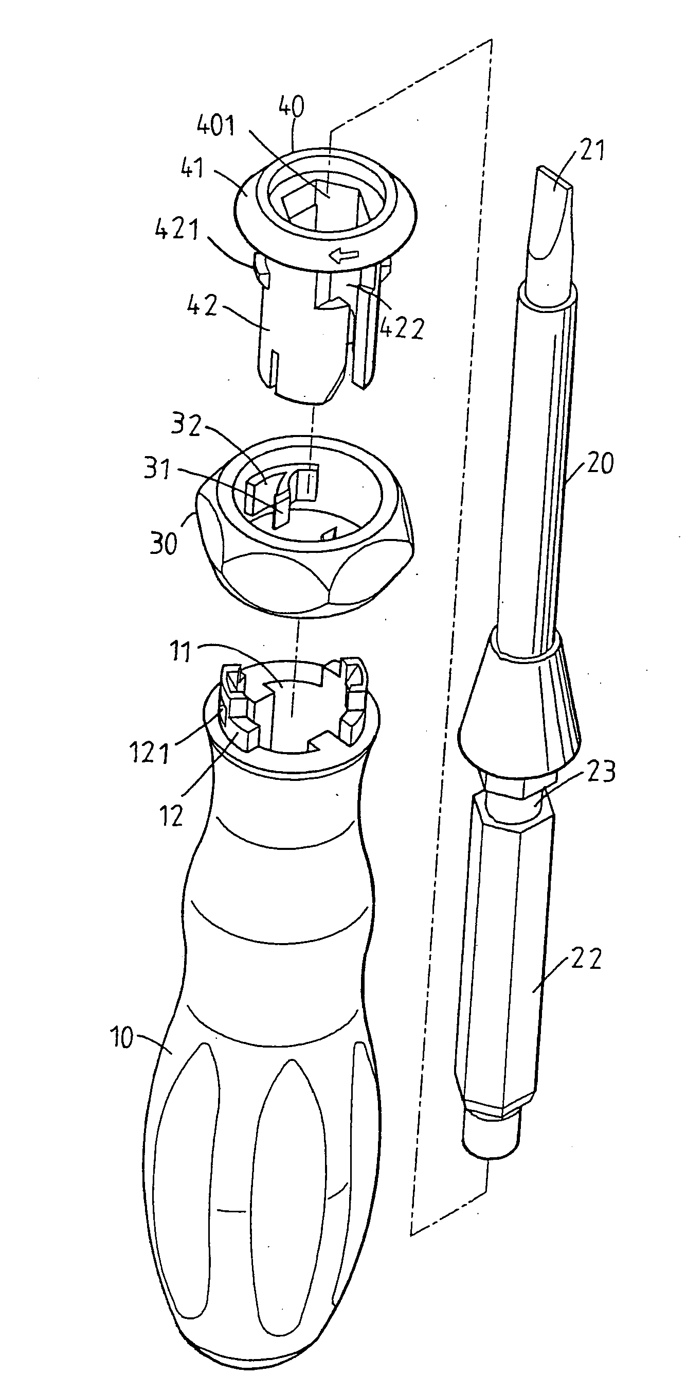
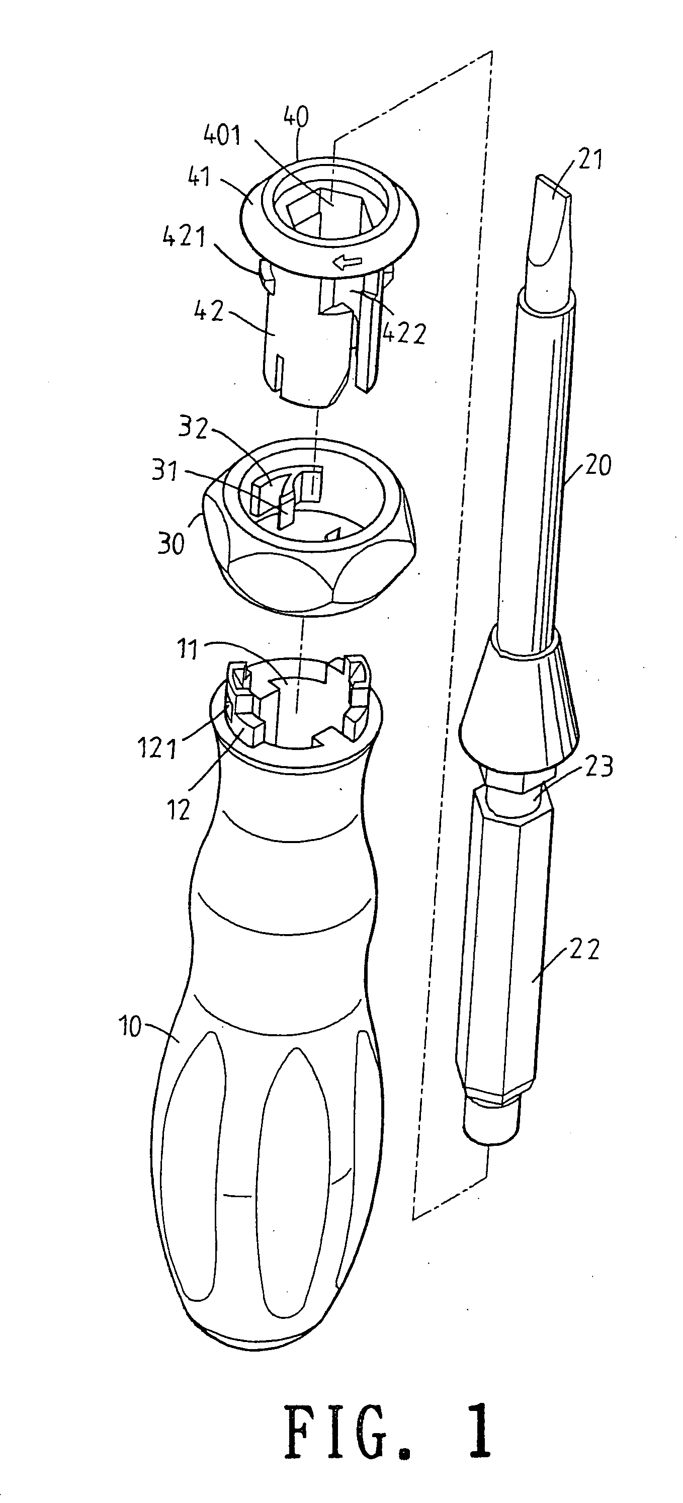
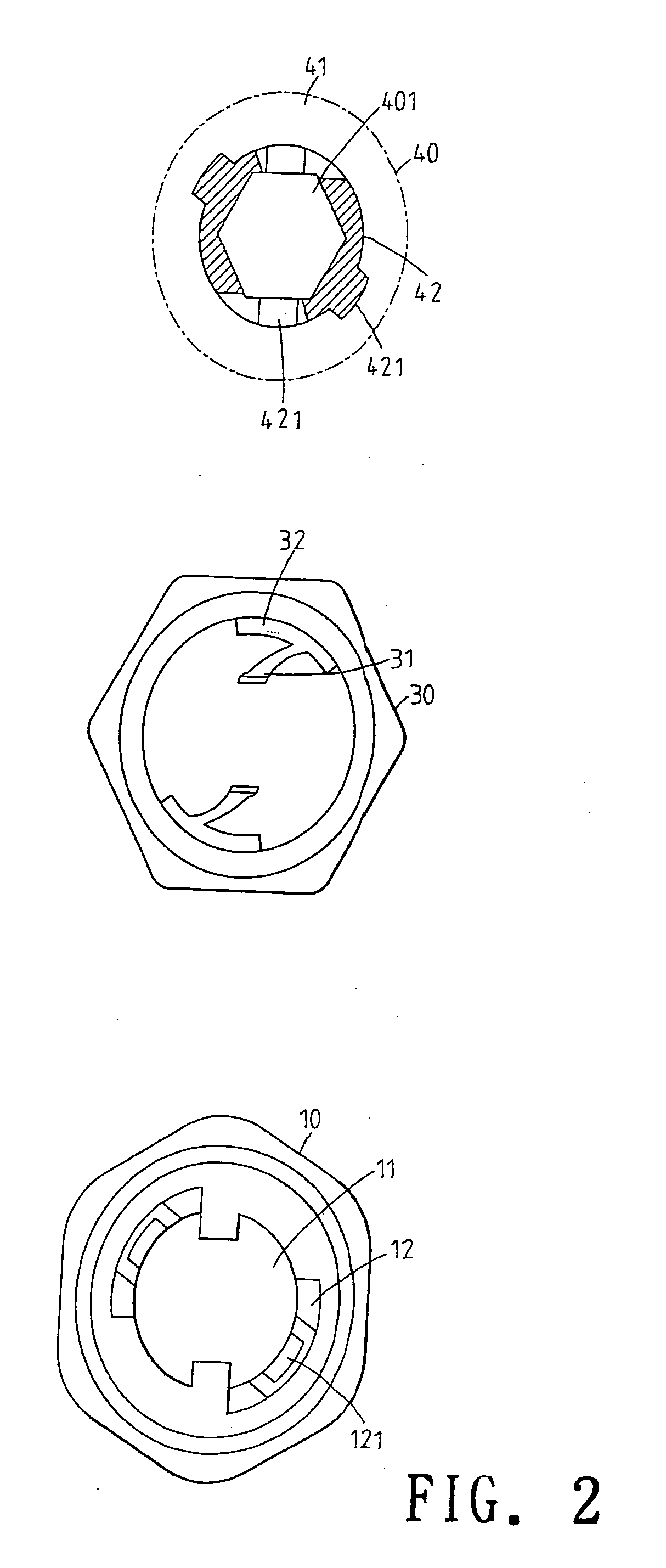
[0014]Referring to FIGS. 1 to 4, the replacement assembly of a handle tool of the present invention is illustrated. The present invention has the following elements.

[0015]An opener head 20 has a driving end 21 and an insertion end 22. An annular recess 23 is formed between the driving end 21 and the insertion end 22. In this embodiment, the driving end 21 is a straight unit. It may have a cruciform, a star shape, hexagonal shape, etc. The insertion end 22 may be a regular polygonal shape.

[0016]The handle 10 has a rod shape. The insertion end 22 may...


PUM


Abstract

A replacement assembly of a handle tool comprises a handle having an axial receiving hole; an adjust unit; the adjust unit being formed with a resisting block; an opener head; the opener head having a buckling groove; a fixing unit installed at one end of the receiving hole for confining the adjust unit; the fixing unit having a positioning hole for receiving an opener head; the fixing unit having at least one through hole which is communicated to the positioning hole; wherein the resisting block enters into the buckling groove of the opener head from the through hole of the fixing unit. The fixing unit has a large head and a small waist; the adjust unit is engaged to the waist and is confined by the head to be combined with the handle.

Description

FIELD OF THE INVENTION[0001]The present invention relates to hand tools, and particularly to a replacement assembly of a handle tool which has a simple structure and can be operated easily and conveniently.BACKGROUND OF THE INVENTION[0002]In a prior art detachable screw improvement structure, an interior of a handle is installed with a recess. The recess is installed with a fixing seat. An interior of the fixing seat has a through hole for receiving an opener rod into the through hole of the fixing seat. A lateral surface of the fixing seat has a recess. A press unit passes through the recess to extend to the through hole and presses the periphery surface of the opener rod so as to position the opener rod. The longitudinal direction of the fixing seat is corresponding to the axial direction of the through hole. Two ends of the longitudinal direction have respective buckling portions. The press unit is a long plate made of compressible and elastic non-metal material. Tow ends corresp...

Claims


Application Information

Patent Timeline
Patent Type & Authority Applications(United States)
IPC IPC(8): B25B23/00B25B23/16
CPCB25B15/02B25G3/18B25G3/04B25B23/0042
Inventor LAI, JIN-TSAI
Owner LAI JIN TSAI
Why Eureka
Try Eureka