Folding shaft for umbrellas

a folding shaft and umbrella technology, applied in the direction of rod connections, fastening means, metal-working hand tools, etc., can solve the problems of significant friction between the sections, affecting the operation of the folding shaft, and defining gaps between sections

Inactive Publication Date: 2008-06-26
GOLDEN RAIN ENTERPRISE
View PDF15 Cites 16 Cited by
  • Summary
  • Abstract
  • Description
  • Claims
  • Application Information

AI Technical Summary

Benefits of technology

[0003]The present invention intends to provide a folding shaft for umbrellas and the sections of the folding shaft includes sections with polygonal shape and sections with circular section, the sections with polygonal shape and sections with circular section are retractably connected to each other in an alternative sequence so as to obtain minimum gap between sections.
[0003]The present invention intends to provide a folding shaft for umbrellas and the sections of the folding shaft includes sections with polygonal shape and sections with circular section, the sections with polygonal shape and sections with circular section are retractably connected to each other in an alternative sequence so as to obtain minimum gap between sections.
[0003]The present invention intends to provide a folding shaft for umbrellas and the sections of the folding shaft includes sections with polygonal shape and sections with circular section, the sections with polygonal shape and sections with circular section are retractably connected to each other in an alternative sequence so as to obtain minimum gap between sections.

Problems solved by technology

However, a gap is defined between the sections and affects the operation of the folding shaft.
Conventional folding shaft of umbrellas generally includes sections each have a circular cross section and the friction between the sections is significant.
If the gaps between the circular sections are made large to reduce the friction and accommodate the spring of the opening device, the spring might not be installed in stable condition.

Method used


Image

  • Folding shaft for umbrellas
  • Folding shaft for umbrellas
  • Folding shaft for umbrellas

Examples


first embodiment

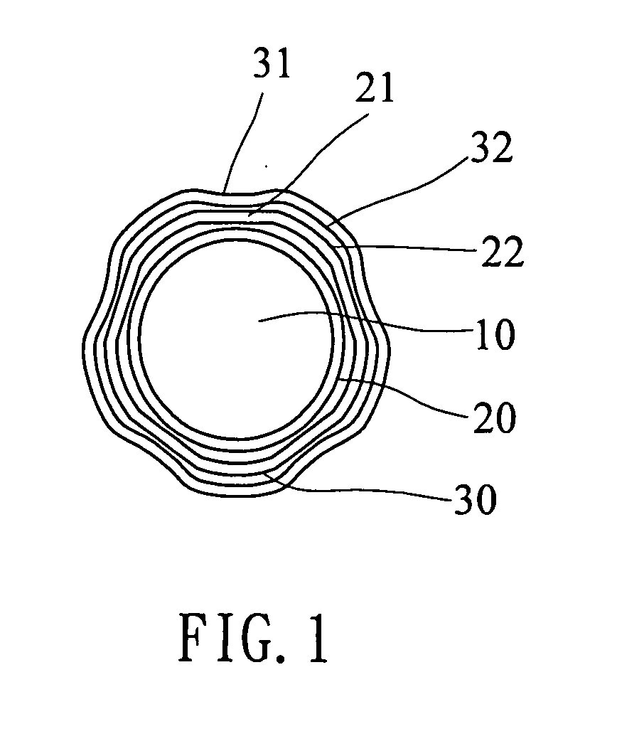
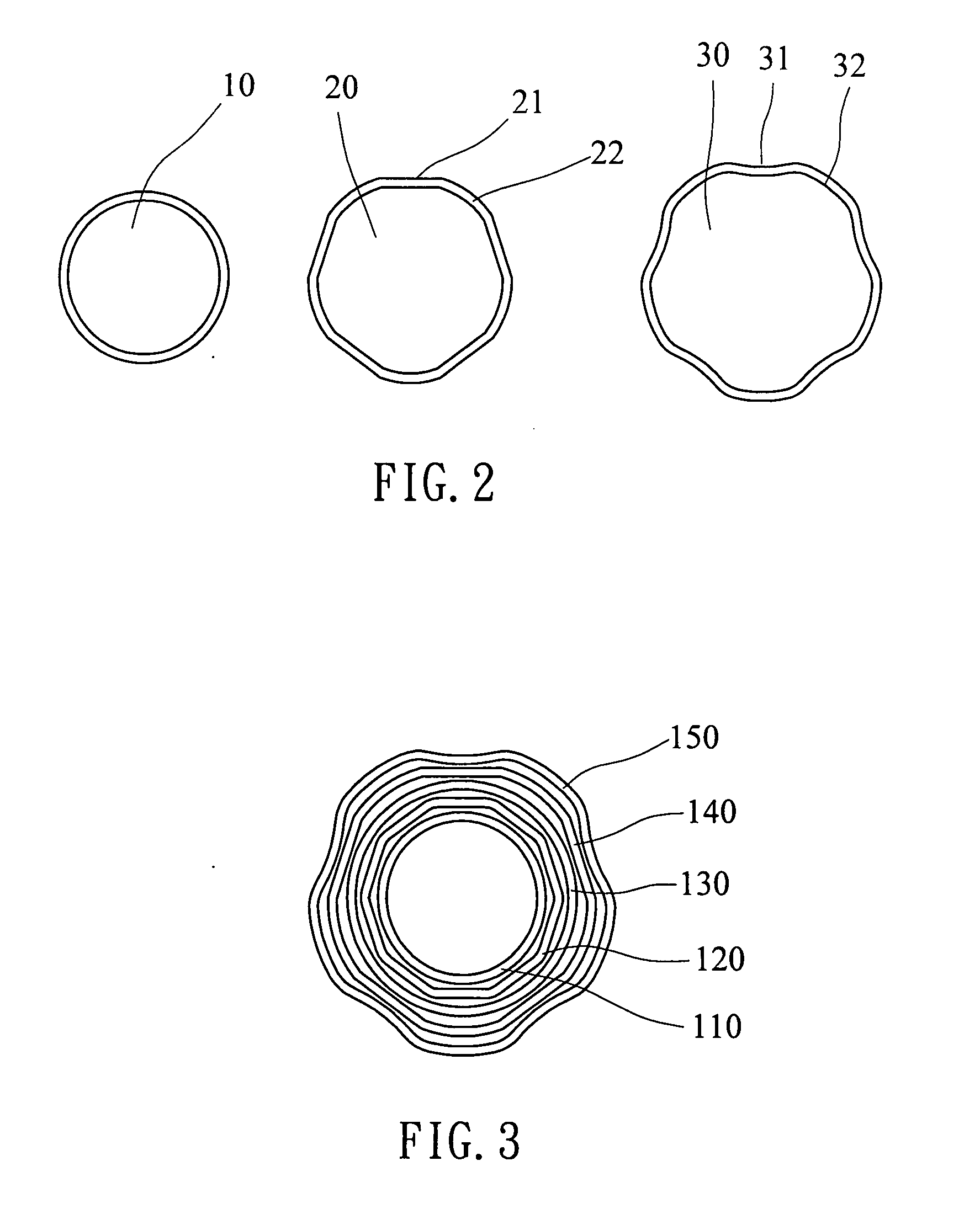
[0013]Referring to FIGS. 1 and 2, the folding shaft of the present invention comprises a first section 10 having a circular cross section, a second section 20 movably mounted to the first section 10 and including an enclosed cross section which includes a plurality of straight sides 21 and a plurality of first curved portions 22 connected between the straight sides 21, and a third section 30 movably mounted to the second section 20 and including an enclosed cross section which includes a plurality of inward curved sides 31 and a plurality of second curved portions 32 connected between the inward curved sides 31. The inward curved sides 31 of the third section 30 are located corresponding to the straight sides 21 of the second section 20, and the second curved portions 32 of the third section 30 are located corresponding to the first curved portions 22. Preferably, the depth of each of the inward curved sides 31 is 1 / 10 to ⅕ of the length of the side. In this embodiment, the second s...

second embodiment

[0014]FIGS. 3 and 4 show the folding shaft of the present invention wherein five sections are involved and includes a first section 110 having a circular cross section, a second section 120 movably mounted to the first section 110 and including an enclosed cross section which includes a plurality of first straight sides and a plurality of first curved portions connected between the first straight sides. A third section 130 is movably mounted to the second section 120 and has a circular cross section. A fourth section 140 is movably mounted to the third section 130 and includes an enclosed cross section which includes a plurality of second straight sides 121 and a plurality of second curved portions 122 connected between the second straight sides 121. The second straight sides 121 of the fourth section 140 are located corresponding to the first straight sides of the second section 120, and the second curved portions 122 of the fourth section 140 are located corresponding to the first...

third embodiment

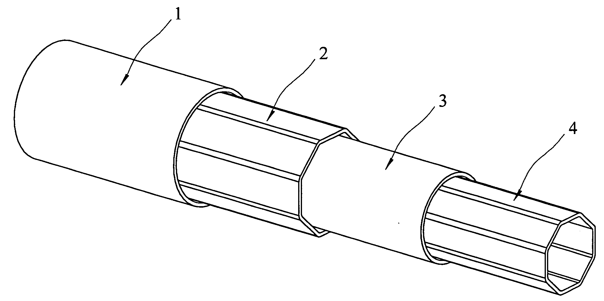
[0015]FIGS. 5, 5a and 5b, the folding shaft of the present invention four sections wherein a first section 1 has a circular cross section and a polygonal section 1a extending from a first end thereof, a notch defined longitudinally in a second end of the first section 1. A second section 2 is retractably received in the first section 1 and includes an enclosed polygonal cross section. Two circular sections 2a are connected to two ends of the second section 2. A third section 3 is retractably received in the second section 2 and includes a circular cross section, two polygonal sections 3a connected on two ends of the third section 3. A fourth section 4 is retractably received in the third section 3 and includes an enclosed polygonal cross section. A circular section 4a is connected to a first end of the second section 2 and a second end of the second section 2 includes a longitudinal opening.

[0016]The gaps between the sections of the folding shaft is controlled to be the minimum so t...


PUM


Abstract

A folding shaft for umbrellas includes a first section having a circular cross section and the first section is retractably received in a second section which includes an enclosed cross section which includes a plurality of straight sides and a plurality of first curved portions connected between the straight sides. A third section is movably mounted to the second section and including an enclosed cross section which includes a plurality of inward curved sides and a plurality of second curved portions connected between the inward curved sides. The inward curved sides of the third section are located corresponding to the straight sides of the second section. The second curved portions of the third section are located corresponding to the first curved portions. The gap between these sections can be controlled to be the minimum.

Description

FIELD OF THE INVENTION[0001]The present invention relates to a folding shaft for umbrellas and the sections of the shaft includes polygonal shape sections and circular shape sections which are be alternatively connected to the sections of polygonal shape.BACKGROUND OF THE INVENTION[0002]A conventional folding shaft of an umbrella generally includes three or four sections which are retractably connected to each other in a sequence such that when the umbrella is not in use, the shaft can be folded to be a short shaft. The foldable shaft is cooperated with an opening device which includes a spring arranged to be extended through the sections of the shaft. In order to smoothly extend or fold the shaft, the inner diameter of each section has to be controlled so as to ensure smooth operation while the opening device can be installed therein. However, a gap is defined between the sections and affects the operation of the folding shaft. Conventional folding shaft of umbrellas generally incl...

Claims


Application Information

Patent Timeline
Patent Type & Authority Applications(United States)
IPC IPC(8): A45B19/04
CPCA45B19/04Y10T403/7077Y10T403/32467A45B9/02A45B19/00A45B25/00
Inventor CHANG, DRAGON
Owner GOLDEN RAIN ENTERPRISE
Why Eureka
Try Eureka