System and method for reducing the borehole gap for downhole formation testing sensors

a technology of formation testing and system and method, which is applied in the direction of survey, borehole/well accessories, directional drilling, etc., can solve the problems of reducing the measurement accuracy, weak impact, and weak impact of shallower looking devices, so as to reduce the borehole gap, little or no

Inactive Publication Date: 2012-04-24
SCHLUMBERGER TECH CORP
View PDF25 Cites 8 Cited by
  • Summary
  • Abstract
  • Description
  • Claims
  • Application Information

AI Technical Summary

Benefits of technology

[0014]A system and method for downhole measurement is disclosed for use with drill strings for reducing the borehole gap with respect to the sensors carried by the drill string. In one embodiment, the sensors are mounted on a surface of the directional drilling hinged pad that comes in contact with the borehole wall. The hinged pad is pressed against the borehole wall as contact is made with the wall, thereby keeping the sensors at a minimum gap with respect to the wall. In another embodiment, the hinged pad is not used for directional drilling. Therefore the pad is extended outward to the wall with the minimum necessary amount of force. That arrangement leads to little or no wear on the sensors. Activation of the hinged pad can be initiated, for example, by flow of mud in the annulus of the string or through a user-provided command. The sensors can include resistivity, density, neutron, electromagnetic, acoustic, seismic, and NMR measurement sensors.

Problems solved by technology

Standoff, or gap, between the sensor and the formation reduces the measurement accuracy and the resultant test data are subject to correction for these gap errors.
Shallower looking devices, however, may be strongly affected by the borehole signal (the error signal caused by the gap), to the extent that, in extreme cases, the formation signal is overwhelmed by the borehole signal and rendered useless.
All of the above-mentioned devices rely on non-rotating sleeves and suffer from at least three limitations.
In the situation when the sleeve is completely stationary, the measurement from the sensor is limited to only one point on the circumference of the borehole wall, leading to limited azimuthal coverage.
Even if the sleeve is slowly rotating, at higher rates of penetration the sensor may sample a helical path along the borehole wall and the resulting measurement will lack full coverage.
Second, the non-rotating sleeve is not used in all directional drilling approaches and may not be present in a drill string equipped with alternate directional drilling technologies that use rotating sleeves.
The third limitation is that the prior art structures are highly vulnerable to breakage when the tool is rotated.
The inherent rugosity of wellbores and motion of the drill collar will cause the pad to be dragged against the wall of the wellbore, placing intolerable loads on the pad.

Method used


Image

  • System and method for reducing the borehole gap for downhole formation testing sensors
  • System and method for reducing the borehole gap for downhole formation testing sensors
  • System and method for reducing the borehole gap for downhole formation testing sensors

Examples


Embodiment Construction

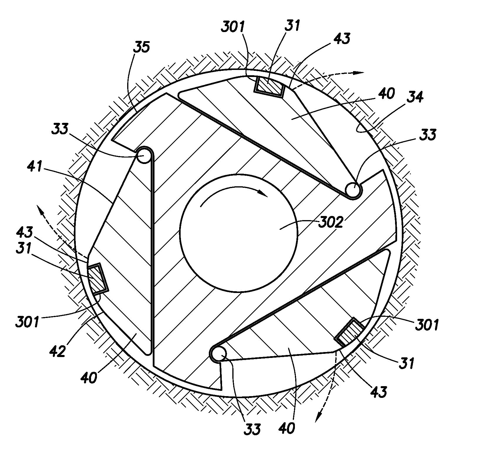
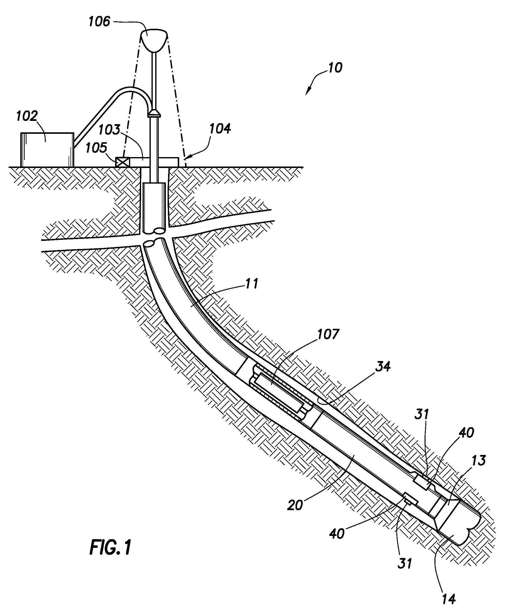
[0023]FIG. 1 shows diagrammatically a typical rotary drilling installation 10 in which the system and method according to the present invention may be employed. In the following description the term “clockwise” refer to the direction of rotation as viewed looking downhole.

[0024]As is well known, the bottom hole assembly includes drill bit 14, and is connected to the lower end of drill string 11 which is rotatably driven from the surface by rotary table 103 on a drilling platform 104. The rotary table is driven by a drive motor, indicated diagrammatically at 105, and raising and lowering of the drill string, and application of weight-on-bit, is under the control of draw works, indicated diagrammatically at 106.

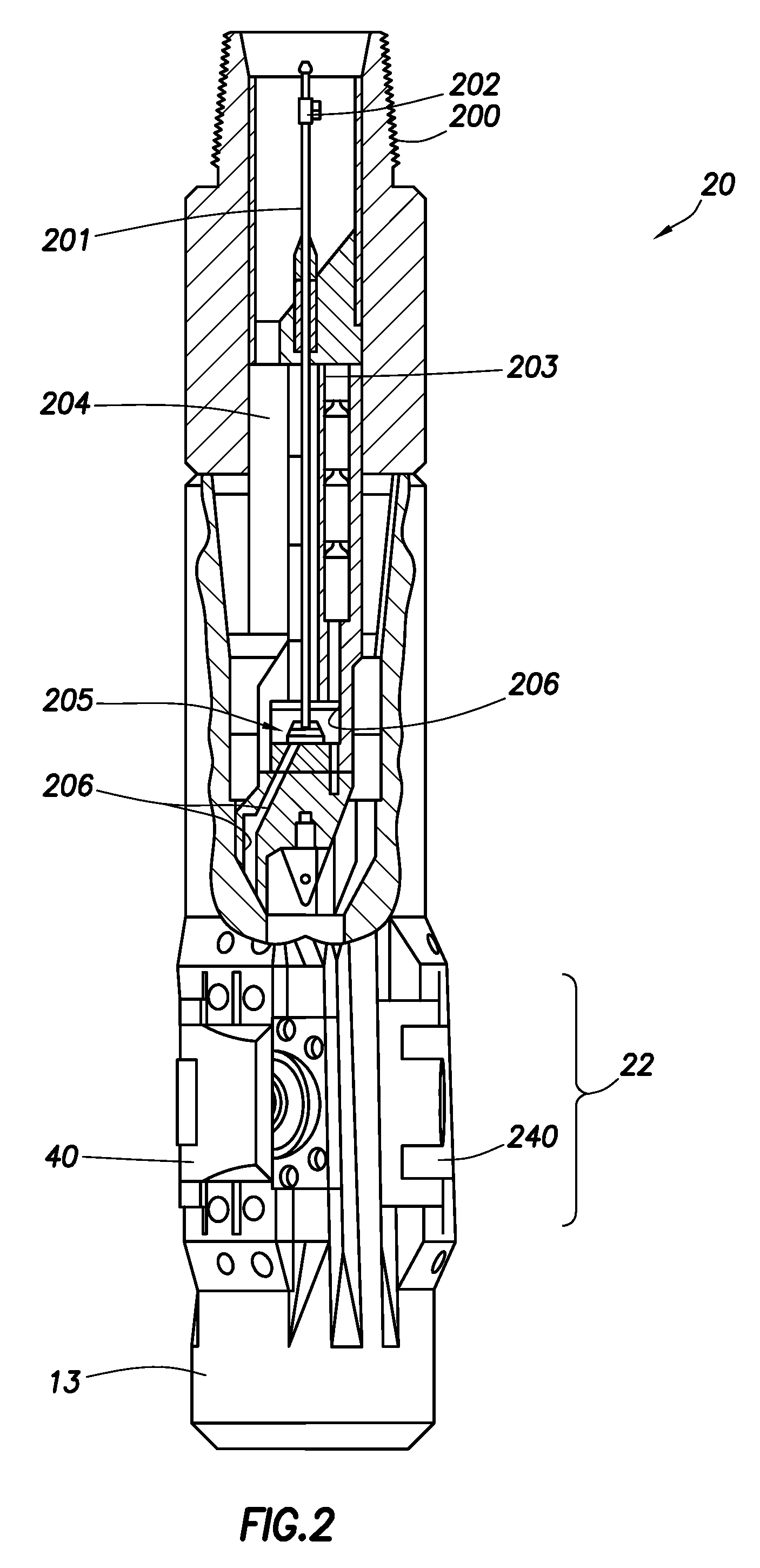
[0025]The bottom hole assembly includes modulated bias unit 20 which drill bit 14 is connected and roll stabilized control unit 107 which controls operation of direction drilling bias unit 20 in accordance with commands provided to the bias unit 20. Directional drilling bias un...


PUM


Abstract

A system and method for downhole measurement for use with drill strings to reduce the borehole gap with respect to sensors carried by the drill string. In one embodiment, the sensors are mounted on a surface of the directional drilling hinged pad that comes in contact with the borehole wall. The hinged pad is pressed against the borehole wall as contact is made with the wall, thereby keeping the sensors at a minimum gap with respect to the wall. In another embodiment, the hinged pad is not used for directional drilling. Therefore the hinged pad is extended outward to the wall with the minimum necessary amount of force. Activation of the hinged pad can be initiated, for example, by flow of mud in the annulus of the string or through a user-provided command. The sensors can include resistivity, density, neutron, electromagnetic, acoustic, seismic, and NMR measurement sensors.

Description

TECHNICAL FIELD[0001]This disclosure relates to making formation measurements while drilling a well, and more particularly to systems and methods for reducing the borehole gap for downhole sensors.BACKGROUND OF THE INVENTION[0002]It is common practice while drilling a borehole to make measurements while drilling (MWD) or to log while drilling (LWD). The sensors used to make such measurements perform much better if they are in close contact with the formation of interest. Standoff, or gap, between the sensor and the formation reduces the measurement accuracy and the resultant test data are subject to correction for these gap errors. Thus, it is desired to place the sensors such that they are in substantial contact with the formation. To achieve such contact, or near contact, sensors are placed on the drill collar, and in some situations, on the outside of the drill collar. Traditionally, deep looking sensors used in LWD and MWD are mounted on the drill collar. In this approach, the s...

Claims


Application Information

Patent Timeline
Patent Type & Authority Patents(United States)
IPC IPC(8): E21B47/00E21B49/00
CPCE21B7/06E21B47/01G01V11/005
Inventor MARTINEZ, RUBENPISONI, ATTILIOSMITS, JAN W.TAHERIAN, REZABITTLESTON, SIMON
Owner SCHLUMBERGER TECH CORP
Why Eureka
Try Eureka