Electrical power or data distribution system

a technology of electric power or data distribution system and power distribution system, applied in the direction of electric digital data processing, coupling device connection, instruments, etc., to achieve the effect of low voltag

Active Publication Date: 2021-08-03
BYRNE NORMAN R
View PDF60 Cites 1 Cited by
  • Summary
  • Abstract
  • Description
  • Claims
  • Application Information

AI Technical Summary

Benefits of technology

[0004]The present invention provides an extremely low-profile distribution system that can be used to route electrical power below carpet or other finishing materials, to deliver low voltage DC power to areas, such as the middle regions of a large rooms, that are normally difficult to supply with power without use of temporary extension cords, raised floor systems, floor trenches, or the like. The system may be reinforced and structurally designed to resist damage from kicking of exposed outlet blocks, from heavy rolling objects such as carts, and from liquid spills or other environmental contamination. Power outlet blocks may be coupled through carpeting or other floor finishing material, to flat electrical conductors beneath the carpeting or finish, or a portion of the carpet or other finish may be cut away to provide access to the flat conductors. Installation is considerably simpler than many other systems, particularly in rooms or other work areas that are already finished with wall surfaces and flooring finishes.
[0016]Accordingly, the flat-conductor electrical power or electronic data distribution system of the present invention facilitates the provision of at least low voltage electrical power and / or electronic data at substantially any desired area throughout a work area or the like. The system utilizes a conductor strip that it sufficiently low in profile to be routed underneath carpeting or other aesthetic finishes, and the use of modular connectors and receptacle blocks facilitates rapid installation with little or no modification to structural floor surfaces, wall panels, or the like, and with minimal tool requirements.

Problems solved by technology

Although some relatively flat and thin wiring systems have been developed for routing along floor and wall surfaces, for example, these have often been susceptible to damage from heavy objects, susceptible to corrosion, or are labor-intensive to set up, install, or connect to a suitable power supply.

Method used


Image

  • Electrical power or data distribution system
  • Electrical power or data distribution system
  • Electrical power or data distribution system

Examples


Embodiment Construction

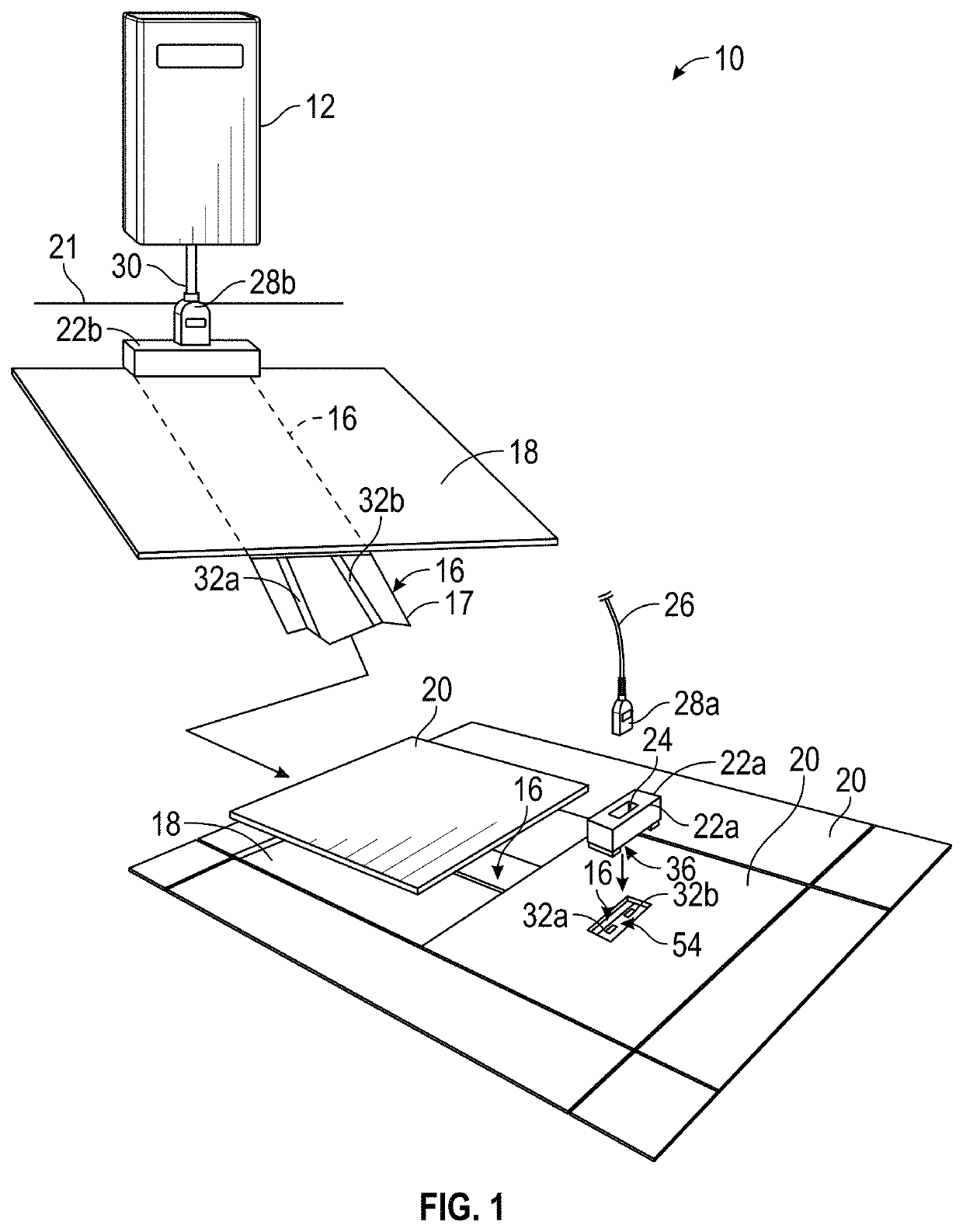
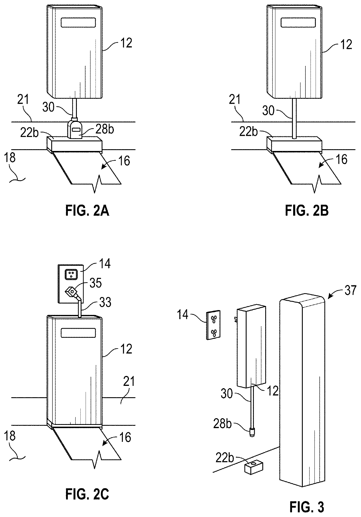
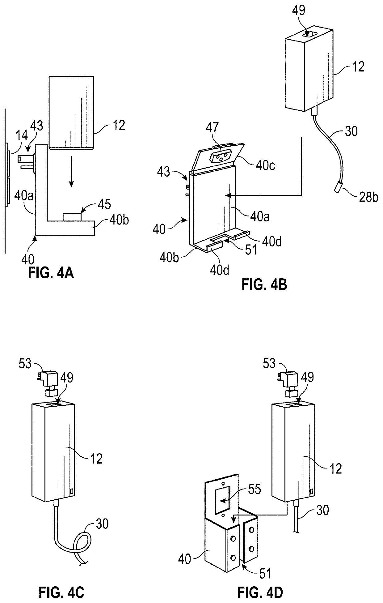
[0042]Referring now to the drawings and the illustrative embodiments depicted therein, an electrical power or electronic data distribution system 10 includes a power supply module 12 that receives electrical power from a power source 14, such as shown in FIGS. 1-4G. Throughout the description and drawings, it will be appreciated that in many cases functionally similar or functionally related or identical components are given identical reference numerals, although their appearance or shape configurations differ. A flat-conductor strip 16 is provided for routing electrical power or electronic data along a generally planar surface such as a floor 18 or a wall, room divider, or ceiling, for example, and may be routed underneath a carpet tile 20 (FIG. 1) or other flooring surface, behind and aesthetic wall molding 21 (FIGS. 1-2C and 5A-5C), or otherwise obscured below or behind an aesthetic covering. The flat-conductor strip 16 terminates at or passes through a power output receptacle bl...


PUM


Abstract

An electrical power or electronic data distribution system includes a power supply or electronic data module that receives electrical power or electronic data signals from a source, a flat-conductor strip for routing electrical power or electronic data along a generally planar surface such as a floor, wall, room divider, or ceiling, and a power or data output block. The power supply has a pair of power outfeed conductors, and the flat-conductor strip has a pair of generally planar electrical conductors in spaced arrangement, which are electrically coupled to respective power outfeed conductors. The output block has a pair of power-receiving contacts along a lower surface thereof, and an electrical receptacle at the output block, the receptacle being positioned above the lower surface. The power-receiving contacts electrically engage respective planar electrical conductors and convey electrical power to respective contacts of the electrical receptacle, for powering electrical or electronic devices.

Description

CROSS REFERENCE TO RELATED APPLICATION[0001]The present application claims the benefit of U.S. provisional application Ser. No. 62 / 587,470, filed Nov. 16, 2017, which is hereby incorporated herein by reference in its entirety.FIELD OF THE INVENTION[0002]The present invention relates to electrical power distribution systems and, more particularly, to electrical power distribution along flooring, walls, and other surfaces in work areas.BACKGROUND OF THE INVENTION[0003]In some areas, particularly finished work areas and the like, it is more convenient to route electrical wiring at or along surfaces in a work area as compared to routing wiring through finished walls, ceilings, or even raised floors, especially when the desired location of electrical and / or electronic data outlets is very specific. Although some relatively flat and thin wiring systems have been developed for routing along floor and wall surfaces, for example, these have often been susceptible to damage from heavy objects...

Claims


Application Information

Patent Timeline
Patent Type & Authority Patents(United States)
IPC IPC(8): H02G3/08H02G3/22H01R9/24H01R12/77G06F13/38H01R12/61H02G3/18
CPCH01R9/2491G06F13/38H01R12/613H01R12/771H02G3/08H02G3/185H02G3/22
Inventor BYRNE, NORMAN R.WARWICK, TIMOTHY J.LAUTENBACH, AARON G.GOLUB, JONATHAN M.ANGULO, JUAN CARLOS
Owner BYRNE NORMAN R
Why Eureka
Try Eureka