
Optical structure for a laser input device

a laser input device and optical structure technology, applied in the direction of instruments, computing, electric digital data processing, etc., can solve the problems of affecting the normal operation of the mouse, the structure of the optical mouse is more complicated, and the operation control precision of the mouse gradually decreases, etc., and achieves higher manufacturing costs than the mechanically driven mous

Inactive Publication Date: 2008-06-26
LEAHSIN TECH +1
View PDF10 Cites 5 Cited by
  • Summary
  • Abstract
  • Description
  • Claims
  • Application Information

AI Technical Summary

Benefits of technology

[0014]One of objects of the invention is to provide an optical structure of a laser input device, which uses a beam-aggregating laser as its light source. Laser light beam is split into two reflected light beams, with the same frequencies, which then intersect with each other to form a light interference strip pattern at intersection. Moving direction and displacement of the input device on a work surface can be determined more precisely by sensing the change of the light interference strip pattern.

Problems solved by technology

Despite of the advantages of mechanically driven mouse such as low technical level and low manufacture cost, the mechanically driven mouse still suffers from wear of the track ball used over a period of time and accumulation of dust and spots inside the mouse, which might adversely affect normal operation of the mouse and operational control precision of the mouse gradually lowers as time elapses.
However, the optical mouse has more complicate structure and thus has higher manufacture cost than the mechanically driven mouse.
Furthermore, the light sensor has light loss problem in receiving the reflected light beams from the objective surface, which leads to insufficient data for image analysis and therefore could not precisely calculate moving direction and displacement for the mouse.
As a result, a cursor on a screen of a computer monitor runs up and down or dislocates, which cannot allow the operational sensitivity of the optical mouse improved and thus disadvantageously lowers the convenience in use.

Method used


Image

  • Optical structure for a laser input device
  • Optical structure for a laser input device
  • Optical structure for a laser input device

Examples


Embodiment Construction

[0024]Wherever possible in the following description, like reference numerals will refer to like elements and parts unless otherwise illustrated.

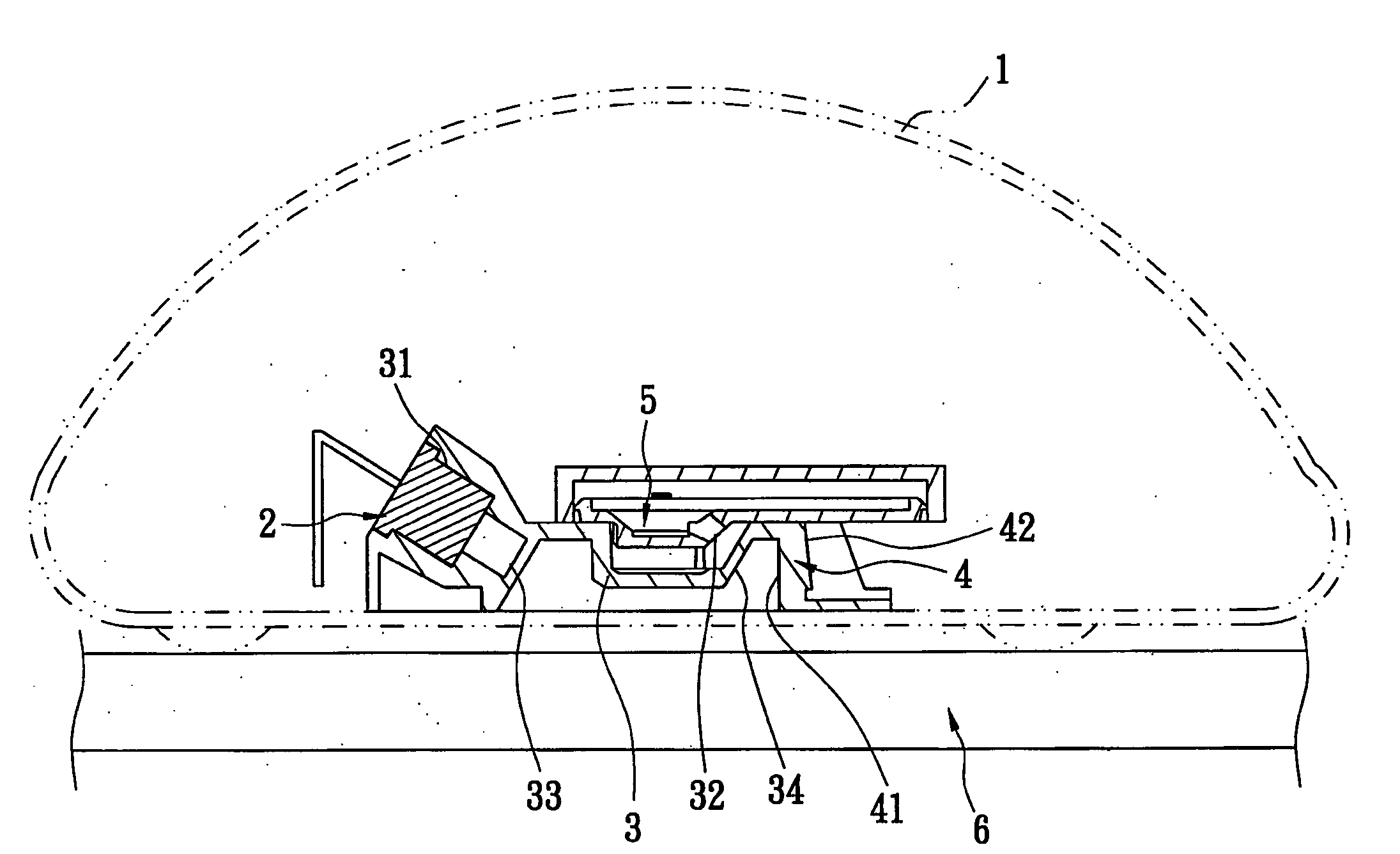
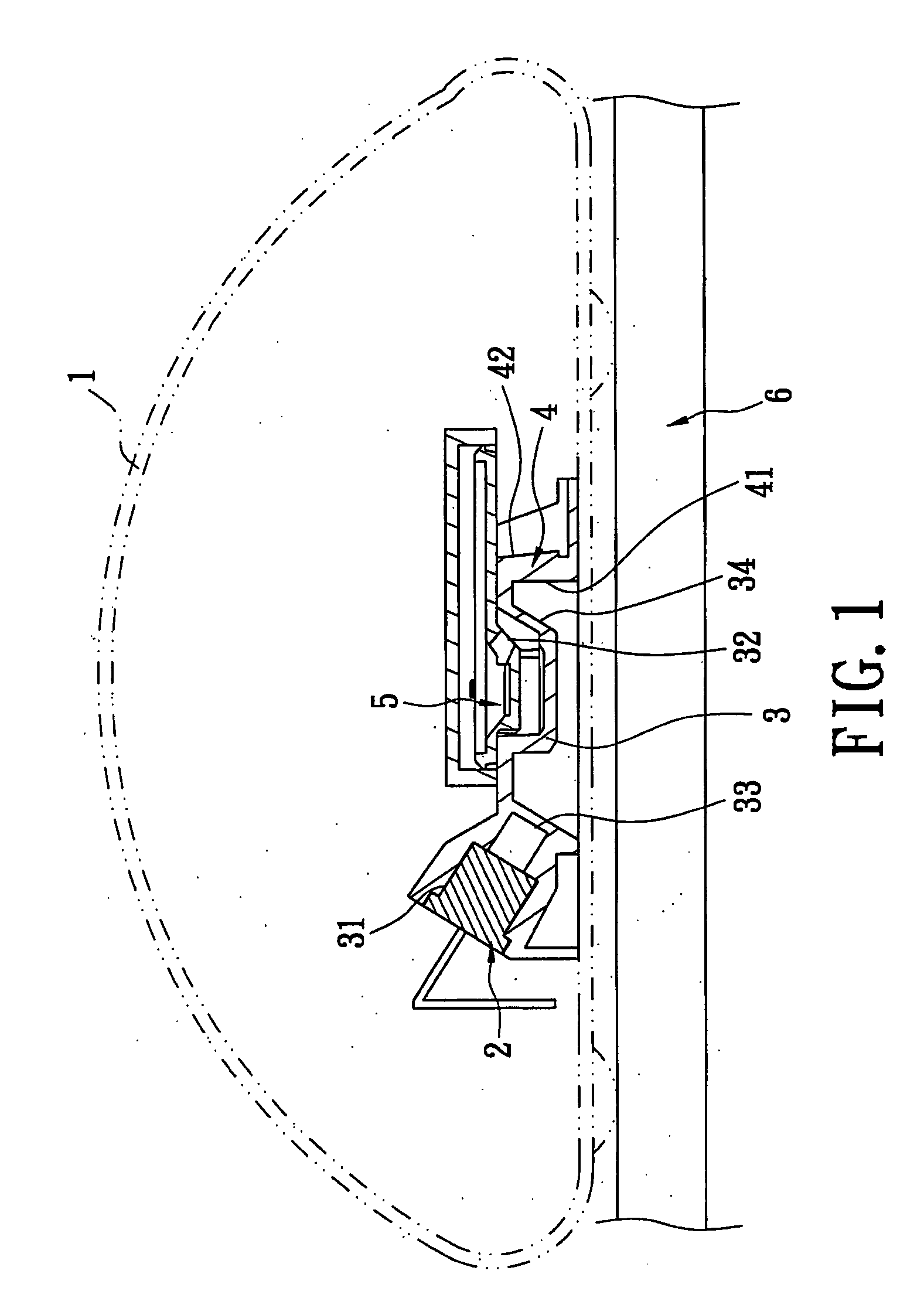
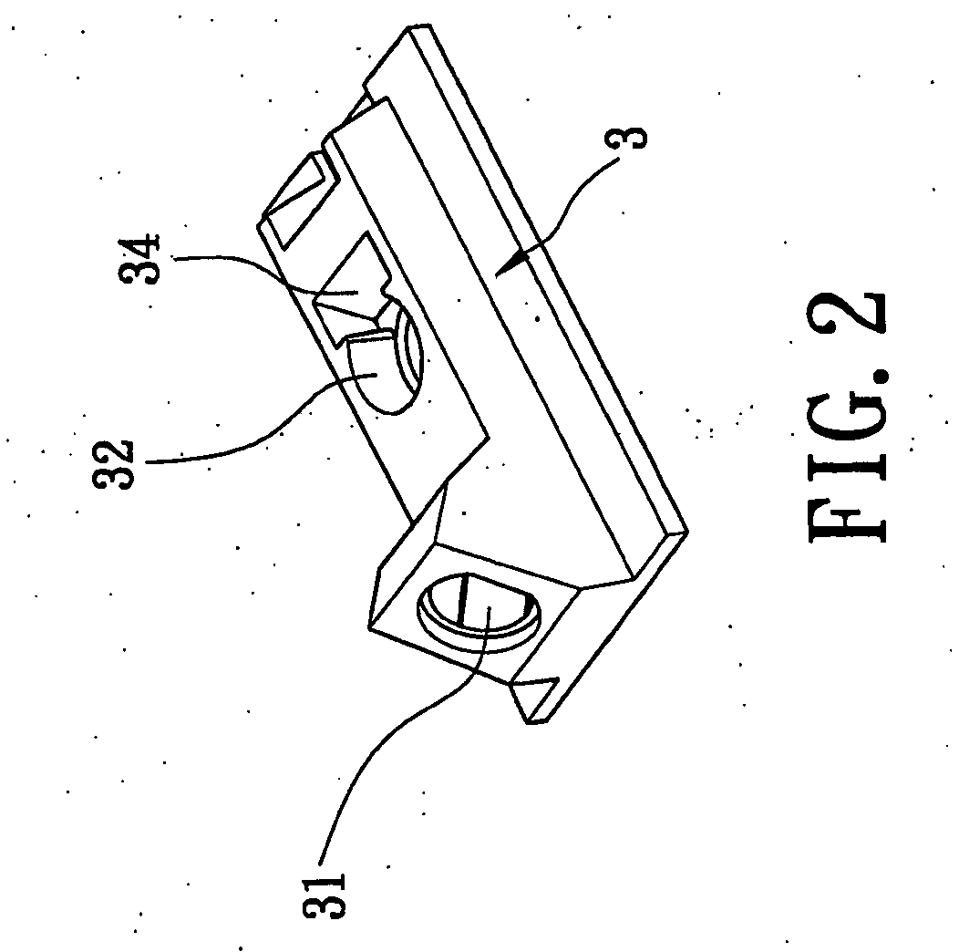
[0025]As shown in FIG. 1, FIG. 2, FIG. 3, FIG. 4, FIG. 5 and FIG. 6, the input device of the invention includes an input device body 1, a laser source 2, a lens base 3, a splitter 4 and a light sensor 5. The laser source 2 is mounted inside the input device body 1 to provide a laser light beam a traveling linearly to a work surface 6 at an incident angle of about 25-45 degree with respect to the work surface 6.

[0026]The splitter 4 is mounted inside the lens base 3 and in the path that the laser beam is reflected. The splitter 4 is in the form of a transparent arrow-headed mirror, having a first interface 41 and a second interface 42 behind the first interface 4 at an angle of 0.1-10 degree between the first interface 41 and the second interface 42. A part of the light beam b reflected by the work surface 6 reaches the first interface 41 and...


PUM


Abstract

An optical structure of a laser input device includes an input device body; a laser source, inside the input device body to emit a laser light beam which travels linearly along a determined incident path to a work surface; a splitter, having a first interface and a second interface behind the first interface, wherein the first interface and the second interface are in a light reflecting path of the laser light beam and reflect respective axial light beams which have the same frequency and intersect with each other; and a light sensor, located at an intersection of the axial light beams for sensing a light interference strip pattern formed by intersecting the axial light beams. Moving direction and displacement of the input device on a work surface can be determined more precisely by sensing the change of the light interference strip pattern.

Description

BACKGROUND OF THE INVENTION[0001]1. Field of the Invention[0002]The invention generally relates to an optical structure of a laser input device. More particularly, the invention relates to an optical structure with a splitter, which splits a light beam into two sub-beams, which have the same frequency and intersect with each other. A light interference strip pattern is formed at the intersection of the two sub-beams. By sensing the change of the light interference strip pattern, data of moving direction and displacement of the input device on a work surface is read to precisely determine the moving direction and displacement of the input device.[0003]2. Description of the Related Art[0004]As the development of technology progresses, personal computer has been playing an important role in our daily life. An input device is essential to the personal computer as a peripheral. The input device such as a mouse and a keyboard has been developing to a new profile in order to catch up with ...

Claims


Application Information

Patent Timeline
Patent Type & Authority Applications(United States)
IPC IPC(8): G06F3/033
CPCG06F3/03543G06F3/0317
Inventor LIN, TIMOTHY
Owner LEAHSIN TECH
Learn More