
Game operating device

a game and operating device technology, applied in the field of game operating devices, can solve the problems of difficult to fix the attitude of the gun, difficult to operate continuously the gun-type controller at a high speed in a stable manner, and difficult to recognize the direction of designation intuitively, and achieve the effect of changing the direction of designation stably and high flexibility

Inactive Publication Date: 2008-06-26
NINTENDO CO LTD
View PDF13 Cites 49 Cited by
  • Summary
  • Abstract
  • Description
  • Claims
  • Application Information

AI Technical Summary

Benefits of technology

[0012]It is another object of the present invention to provide a game operating device that is easy to operate while holding it by one hand and makes it easy to recognize the direction of designation.
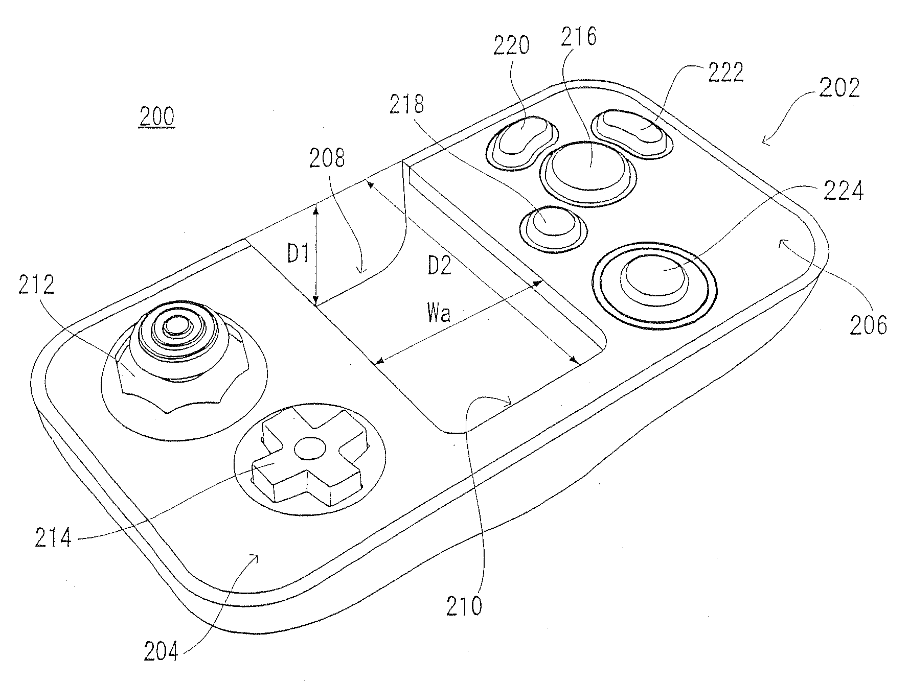
[0034]According to the present invention, it is easy to operate the first operating portion and the second operating portion while holding the controller by one hand, which makes it possible to obtain a novel game operating device that is high in flexibility and capable of being operated only by one hand. Additionally, the imaging range of the imaging means contains the direction along the longitudinal direction of the holding portion, which makes it possible to recognize or grasp intuitively the direction of designation of the imaging means while holding the housing.

Problems solved by technology

Thus, it is difficult to recognize intuitively the direction of designation only with a sensation in the hand holding the grip.
However, the barrel significantly extends off the holding portion, which causes a problem where the center of gravity of the entire gun cannot be firmly held and thus it is hard to fix the attitude of the gun.
Furthermore, with occurrence of shakes due to trigger operation, it is difficult to operate continuously the gun-type controller at a high speed in a stable manner.

Method used


Image

  • Game operating device
  • Game operating device
  • Game operating device

Examples


Embodiment Construction

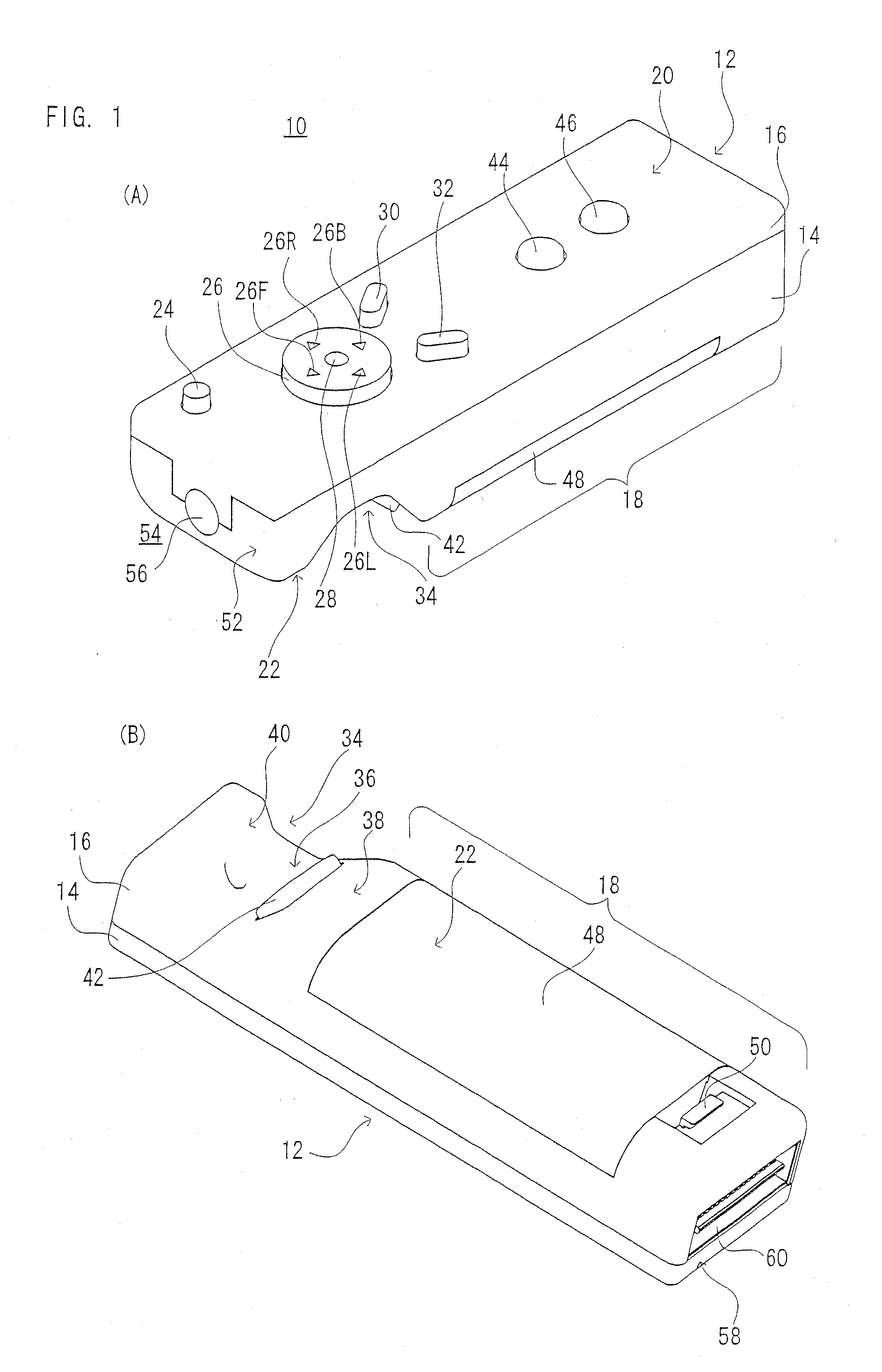
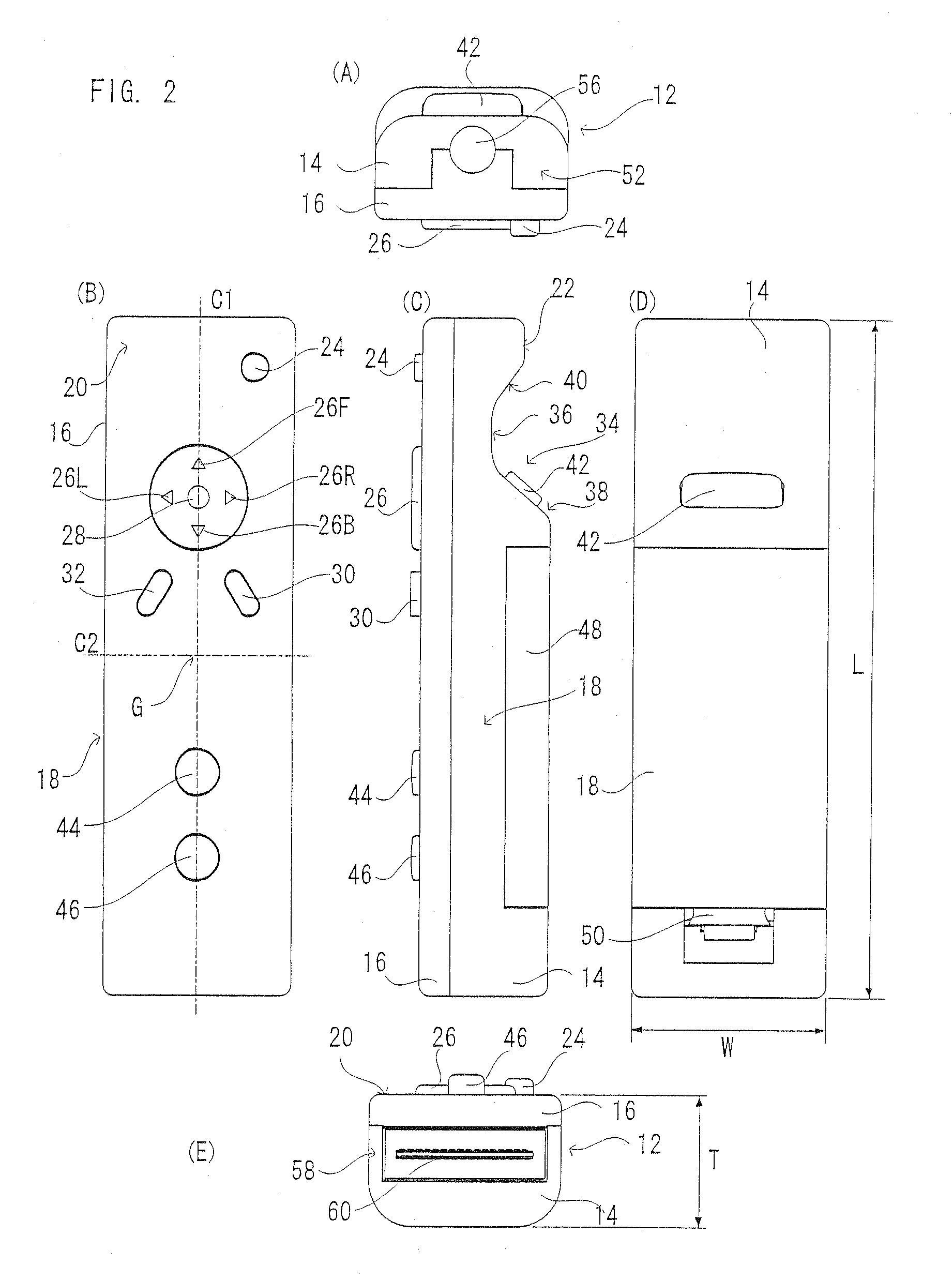
[0068]A controller 10 of one embodiment of the present invention shown in FIG. 1 and FIG. 2 includes a longitudinal housing 12 molded of plastic or metal, for example. The housing 12 has a required depth and includes a lower housing 14 having a shape of a flat rectangle with a top-surface opening and an bottom, an upper housing 16 assembled integrally with the lower housing 14 in such a manner as to close up the top-surface opening of the lower housing 14, and in particular, has a cross-section rectangle on the whole as shown in FIG. 2 (A) and FIG. 2 (E).

[0069]The housing 12 has a holding portion 18 and is of size capable of being held by one hand of an adult or child on the whole. Its length L (FIG. 2 (D)) in a longitudinal direction (a direction along a center line C1 shown in FIG. 2 (B)) is set at 8 to 15 cm, for example, and its width (orthogonal to the longitudinal direction C1) W (FIG. 2 (D)) is set at 2 to 4 cm, for example, respectively.

[0070]Alternatively, the shape of the ...


PUM


Abstract

A game operating device (controller) includes a longitudinal housing, and a holding portion held by hand to be wrapped by its palm it is formed in the housing. A direction switch is provided on an upper surface at a position where it can be operated by thumb of the hand holding the holding portion, and a start switch and a select switch are provided backward thereof. An X button 46 and a Y button are further arranged in line on the upper surface of the housing. An imaging information arithmetic unit is provided at a front end of the housing in a longitudinal direction in such a manner that an imaging device thereof is exposed from a front-end surface. A concave portion is formed on a lower surface at a position corresponding to the direction switch. The concave portion includes a valley and two inclined surfaces. An A button capable of being operated by index finger of the hand holding the holding portion is provided on the backward inclined surface. By processing an image signal obtained by imaging an infrared ray from LED modules by the imaging device, it is possible to obtain an operation signal varying according to a position and / or attitude of the controller.

Description

CROSS REFERENCE OF RELATED APPLICATION[0001]This application is a continuation of application Ser. No. 11 / 446,188, filed Jun. 5, 2006, the entire content of which is hereby incorporated by reference in this application. The disclosure of Japanese Patent Application No. 2005-239984 is also incorporated herein by reference.BACKGROUND OF THE INVENTION[0002]1. Field of the Invention[0003]The present invention relates to a game operating device. More specifically, the present invention relates to a game operating device that analyzes movements of an operating device through detection of a predetermined mark or pattern in an image taken by an imaging device.[0004]2. Description of the Related Arts[0005]Some operating devices as related arts of this kind of game operating device are disclosed in Japanese Patent No. 3422383 and Japanese Patent Laying-open No. 2002-233665.[0006]The related art disclosed in Japanese Patent No. 3422383 makes it possible to play a shooting game by arranging lig...

Claims


Application Information

Patent Timeline
Patent Type & Authority Applications(United States)
IPC IPC(8): A63F9/24A63F13/213A63F13/219A63F13/235A63F13/24
CPCA63F13/06A63F2300/1006A63F2300/1087A63F2300/105A63F2300/1043A63F13/213A63F2300/308A63F2300/558A63F13/98A63F13/533A63F13/211A63F13/235A63F13/24A63F13/23
Inventor IKEDA, AKIOKURODA, RYOJIURATA, MASAHIRO
Owner NINTENDO CO LTD
Learn More