Syringe with retractable needle support

a technology of syringes and needle supports, which is applied in the field of disposable syringes, can solve the problems of syringes that are disposable and present a significant problem to users, refuse handlers and other persons who might inadvertently come into contact with used hypodermic syringes, and are quickly thereafter discarded properly

Inactive Publication Date: 2008-06-26
STAT MEDICAL DEVICES
View PDF65 Cites 18 Cited by
  • Summary
  • Abstract
  • Description
  • Claims
  • Application Information

AI Technical Summary

Benefits of technology

[0013]According to one non-limiting aspect of the invention there is provided a hypodermic syringe having a plunger which can, in one orientation, be moved to the full depth position so as to allow essentially all of the contents of the syringe to be injected without causing the plunger to become locked with the needle support or the needle support hub and, in another orientation, a plunger can be moved to the full depth position so as to allow essentially all of the contents of the syringe to be injected while also causing the plunger to become locked with the needle support or the needle support hub. If the user desires, the plunger, while in the full depth position, can be rotated to cause unlocking of the plunger and needle support or can be rotated to cause locking of the plunger and needle support.
[0015]The invention also provides for a syringe whose needle support and / or needle support hub is capable of being easily and simply retracted to a safe position within the barrel where the needle is withdrawn to an enclosed and protected position preventing the possibility of inadvertent needle pricks.
[0021]The locking arrangement may selectively lock a proximal end portion of the plunger to the needle support. The locking arrangement may selectively lock the proximal end portion of the plunger to the needle support upon rotation of the plunger. The locking arrangement may selectively lock the proximal end portion of the plunger to the needle support only upon rotation of the plunger. The locking arrangement may selectively lock the proximal end portion of the plunger to the needle support upon rotation of the plunger to a predetermined position. The locking arrangement may selectively lock the proximal end portion of the plunger to the needle support upon rotation of the plunger to a position approximately transverse to an initial unlocked position. The plunger may be movable to a full insertion or to a full injection position without causing the proximal end portion of the plunger to become locked to the needle support. The plunger may be movable to an injection position which minimizes a dead space without causing the proximal end portion of the plunger to become locked to the needle support. The plunger may be movable to an injection position which causes contact between a piston of the plunger and an internal shoulder of the barrel without causing the proximal end portion of the plunger to become locked to the needle support. The plunger may be movable to an injection position which causes contact between a portion of the plunger and an internal shoulder of the barrel without causing the proximal end portion of the plunger to become locked to the needle support.
[0029]The invention also provides for a method of using any of the injection devices described above, wherein the method comprises moving the plunger away from the needle support so as to cause a desired amount of medicine to enter into the barrel, moving the plunger towards the needle support so as to cause medicine to exit the barrel through the needle support and so as to position the plunger at least one of at a full injection position and at a position substantially eliminating a dead space in the syringe, again moving the plunger away from the needle support, and locking the proximal end portion of the plunger to the needle support by rotating the plunger from a first position to a second position.
[0033]The invention also provides for a method of using any of the injection devices described above, wherein the method comprises moving the plunger away from the needle support so as to cause a desired amount of medicine to enter into the barrel, moving the plunger towards the needle support so as to cause medicine to exit the barrel through the needle support and so as to position the plunger at least one of at a full injection position and at a position substantially eliminating a dead space in the syringe, again moving the plunger away from the needle support, and locking the proximal end portion of the plunger to an outer portion of the needle support after the plunger is moved to a full injection position.

Problems solved by technology

After hypodermic syringes have been used in this manner, those syringes that are disposable present a significant problem to users, e.g., hospital or nursing home staff, because the possibility of inadvertent needle pricks subject personnel to the possibility of cross-contamination by, among other things, virile or bacterial contaminants that might be present on the needle after its use.
Further, refuse handlers and other persons who might inadvertently come into contact with the used hypodermic syringes are also subject to the same hazards.
In certain situations, medicaments are injected into patients and not quickly thereafter discarded properly.
However, between the time of use and the time of disposal, there is the possibility that inadvertent needle pricks will occur.
During injection, however, the plunger irreversibly locks to the needle support when the plunger is moved to the full depth position.
Furthermore, the plunger cannot be moved to the full depth position without causing engagement of the lock system.
This means that there will be a dead space in the syringe if the plunger is not moved to the full depth position.
However, during injection, the plunger irreversibly locks to the needle support when the plunger is moved to the full depth position.
Furthermore, the plunger cannot be moved to the full depth position without causing engagement of the lock system.
This means that there will be a dead space in the syringe if the plunger is not moved to the full depth position.
However, during injection, the plunger irreversibly locks to the needle support hub when the plunger is moved to the full depth position.
Furthermore, the plunger cannot be moved to the full depth position without causing engagement of the lock system.
This means that there will be a dead space in the syringe if the plunger is not moved to the full depth position.

Method used


Image

  • Syringe with retractable needle support
  • Syringe with retractable needle support
  • Syringe with retractable needle support

Examples


Embodiment Construction

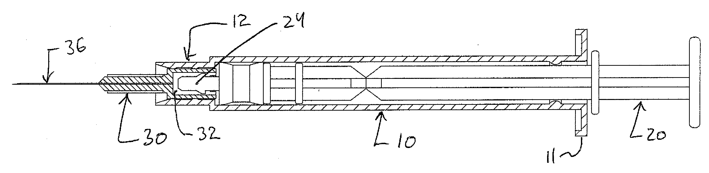
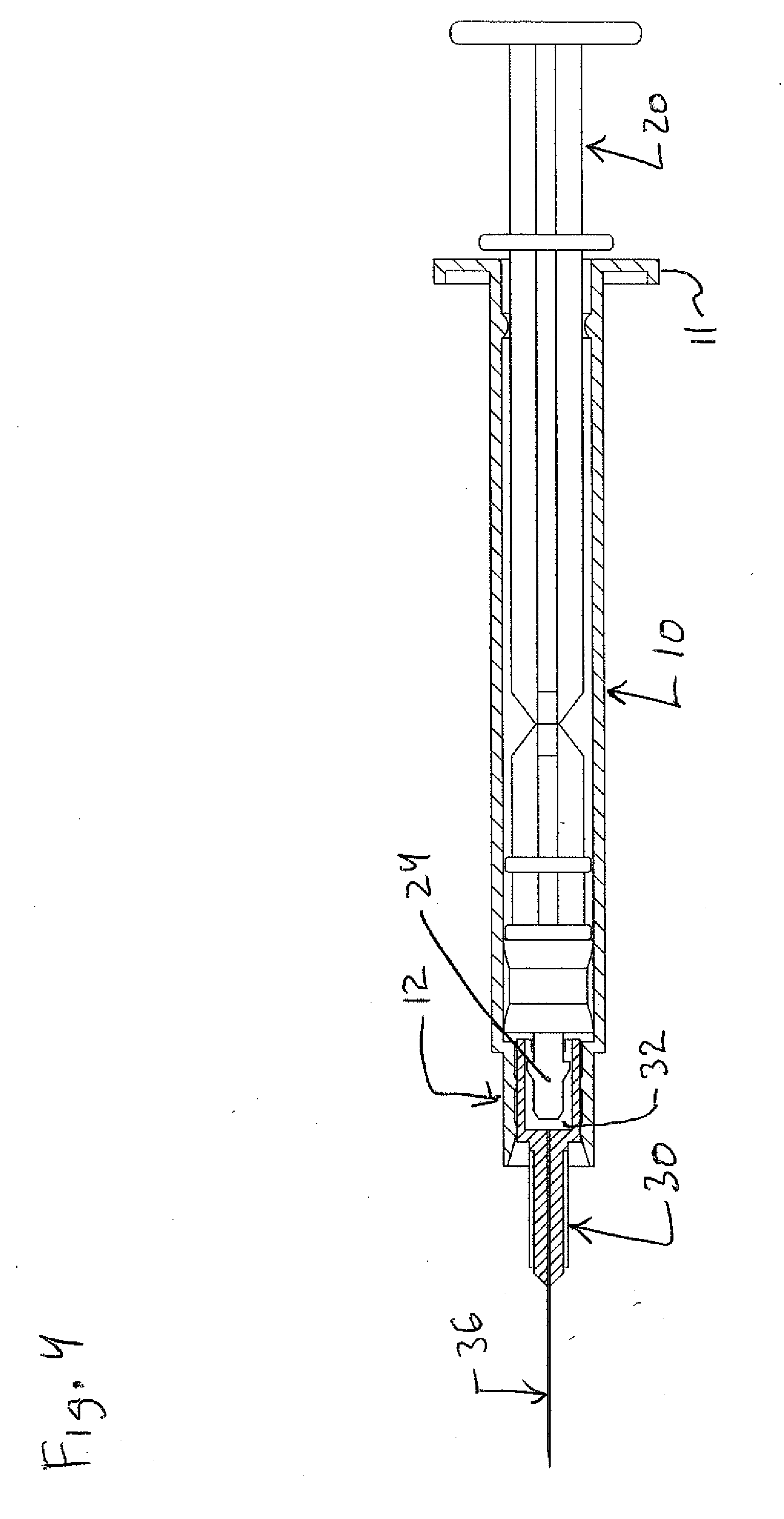
[0076]Referring now to the drawings and first to FIG. 4 which shows a first embodiment of a retractable hypodermic syringe. The syringe includes a generally elongate cylindrical barrel 10 having a transverse flange 11 arranged at a distal end of the barrel 10. The proximal end of the barrel 10 includes a reduced diameter section 12 which forms a tubular extension and / or a cylindrical sleeve which is disposed concentrically about a proximal end passage 13 (see FIG. 11) that extends through the section 12 and into a main internal chamber 14 defined by the main cylindrical section of the barrel 10.

[0077]A needle support 30 is normally positioned within the passage 13 (see FIG. 11) and includes a rear end portion 31 (see FIG. 14) which is sealed to and / or in frictional engagement with the cylindrical section 12. As shown in FIG. 1, the rear end portion 31 of the needle support 30 includes a main opening 32 configured to receive therein a front or proximal end portion 24 of the plunger 2...


PUM


Abstract

An injection device includes a barrel, a plunger having a portion structured and arranged to move within the barrel, a needle support, and a locking arrangement. The locking arrangement may at least one of selectively lock a proximal end portion of the plunger to the needle support and automatically lock a proximal end portion of the plunger to an outer portion of the needle support. This Abstract is not intended to define the invention disclosed in the specification, nor intended to limit the scope of the invention in any way.

Description

BACKGROUND OF THE INVENTION[0001]1. Field of the Invention[0002]This invention relates generally to syringes, e.g., hypodermic syringes, such are utilized for injection of medicament into the body tissues of human and animal patients. More specifically, this invention relates to a hypodermic syringe having a plunger, piston and needle support structure that permits retraction of the needle support and its needle into the barrel of the syringe to prevent the possibility of inadvertent needle pricks and which incorporates a frangible plunger that may be broken away to prevent subsequent actuation of the needle to its operative position.[0003]This invention also relates to syringes which have minimal dead-space so that they can be ideally used for injecting very expensive medicaments with minimal waste.[0004]This invention also relates to syringes which can be used only once, i.e., single-use syringes, and / or to syringes which utilize a rotating releasable lock system for locking the p...

Claims


Application Information

Patent Timeline
Patent Type & Authority Applications(United States)
IPC IPC(8): A61M5/315
CPCA61M5/5066A61M5/322
Inventor SCHRAGA, STEVEN
Owner STAT MEDICAL DEVICES
Why Eureka
Try Eureka