
Method and Device For Analyzing a Technical Process

Active Publication Date: 2008-06-26
SIEMENS AG
View PDF2 Cites 2 Cited by
  • Summary
  • Abstract
  • Description
  • Claims
  • Application Information

AI Technical Summary

Benefits of technology

[0009]The object underlying the invention is therefore to specify a method and a device for analyzing a technical process which, even in the case of a large distance between a central detection unit and the measuring and image detection units, allows highly accurate time synchronization of the image and measuring data.
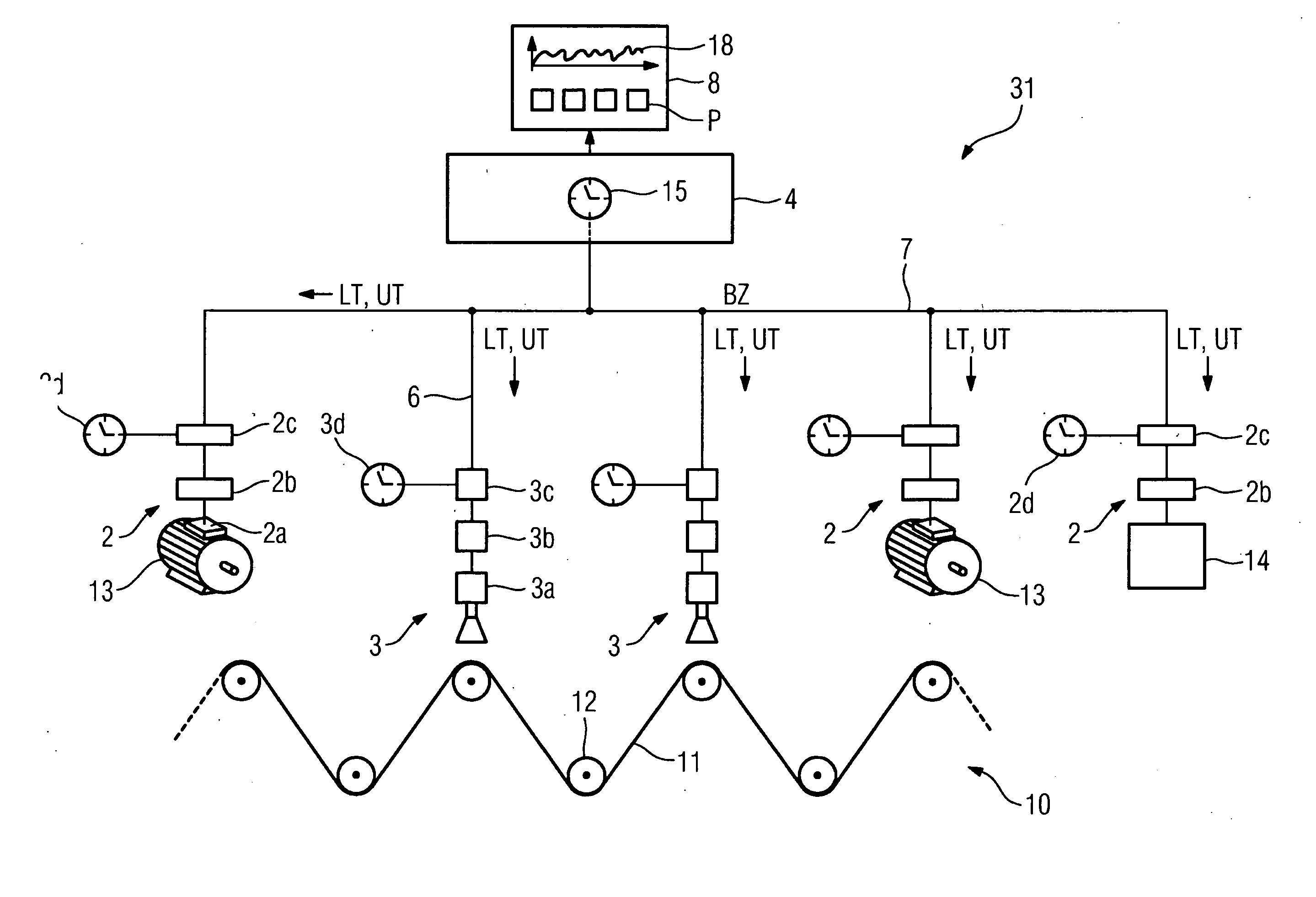
[0011]The invention turns away from the previous approach of performing time stamping of the measuring and image data in the central detection unit. Instead time stamping accordingly takes place directly in situ, i.e. decentrally, in the measuring and image detection units. Since the measuring and image data is already provided with the time stamp in the decentralized units, the data transmission time to the central detection unit is not critical. Since, moreover, the time stamp is available to all measuring and image data detection units this also ensures that events that occur at the same time for example are provided with the same time stamp, i.e. with the same time indications, by both the measuring units and image detection units. Highly accurate time synchronization of the measuring and image data is therefore possible in the central detection unit with the aid of the time stamp, so images and measured values in the range of microseconds or less can be displayed or processed further in a time-synchronous manner.

Problems solved by technology

However, with measuring and image detection units that are located a long way (for example several hundred meters or more) from the central detection unit there exists the problem that, for example owing to the different running times of the data from the decentralized measuring and image detection units to the central detection unit, time stamping exhibits a certain indistinctness, so sometimes a clear statement on the sequence over time of the data issued by the measuring and image detection units is not possible.
This leads to indistinctness in the time-synchronous allocation of the image data to the measuring data.

Method used


Image

  • Method and Device For Analyzing a Technical Process
  • Method and Device For Analyzing a Technical Process
  • Method and Device For Analyzing a Technical Process

Examples


Embodiment Construction

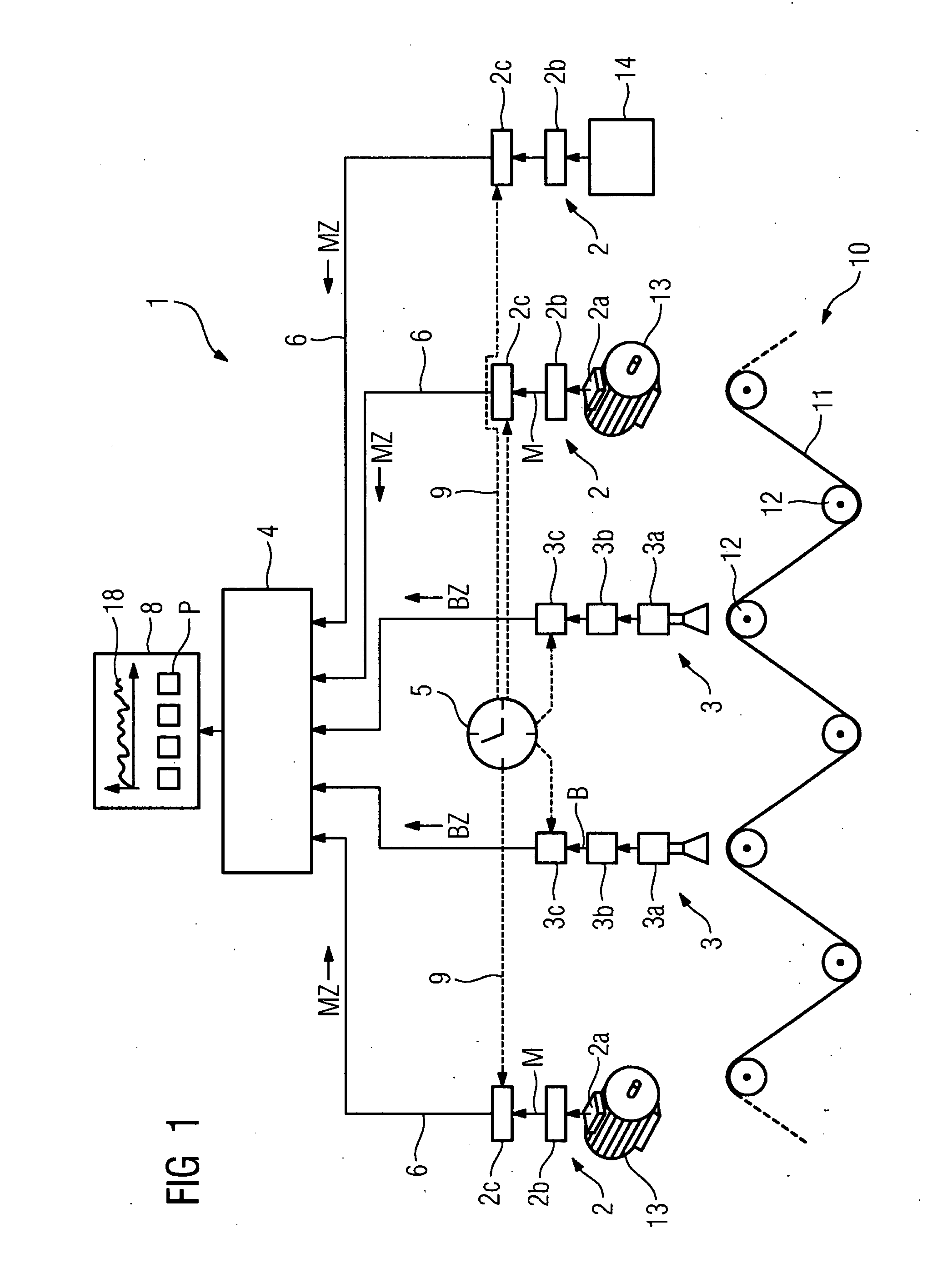
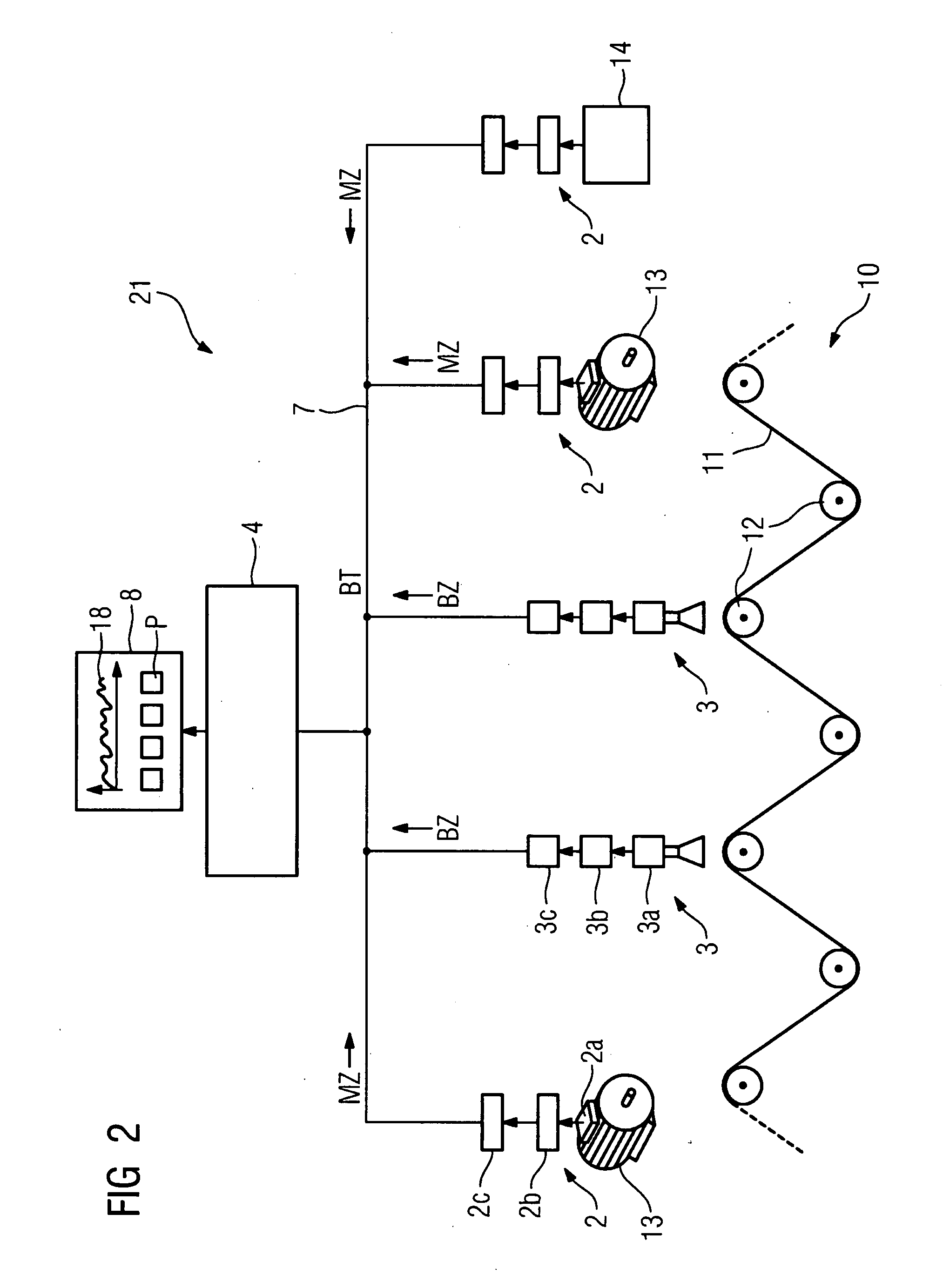
[0031]FIG. 1 shows a device 1 for analyzing a technical process 10. The technical process 10 is a manufacturing process for continuous material 11, such as paper, which, guided by winders 12, runs through a plant (not shown) that is distributed over a wide area for producing the continuous material 11. A large number of driving, energy-supplying and automating components are required for the manufacturing process, of which only two motors 13 and an automation component 14 are shown by way of example in FIG. 1.

[0032]Using measuring units 2 measuring signals from the motors 13 and the automating component 14 are detected and transmitted as measuring data to a central detection and evaluation unit 4 via connecting lines 6. The measuring units 2 can, for example, comprise a signal transmitter 2a which passes measuring signals to a device 2b which generates measuring data M from the measuring signals for transmission to the central detection and evaluation unit 4. Each of the measuring u...


PUM


Abstract

A method for analyzing technical processes is disclosed, which is characterized in that measuring data of the technical process is generated by at least one decentralized measuring unit, image data associated with a mechanical course of the technical process is produced by at least one decentralized image detection unit, the measuring data stored in the at least one decentralized measuring unit and the image data stored in the at least one image detection unit is provided with a time stamp available to all systems, the measuring and image data are transmitted to a central detection unit where said data is displayed and / or processed in a time-synchronous manner using the time stamp function. Since time stamping is carried out directly in situ, i.e. decentrally in the respective measuring and image detection units, data transmission time required to transmit data to the central detection unit is not critical, so that a time-synchronized display and / or further processing of the measuring and image data can be carried out in the central detection unit with a high degree of accuracy.

Description

CROSS REFERENCE TO RELATED APPLICATIONS[0001]This application is the US National Stage of International Application No. PCT / EP2005 / 055110, filed Oct. 7, 2005 and claims the benefit thereof. The International Application claims the benefits of German application No. 10 2004 050 386.9 filed Oct. 15, 2004, both of the applications are incorporated by reference herein in their entirety.FIELD OF INVENTION[0002]The invention relates to a method and to a device for analyzing a technical process.BACKGROUND OF THE INVENTION[0003]For analyzing technical processes, such as industrial manufacturing processes, it is already known to detect measuring data from the process as well as images of the process and to display these on-line or off-line.[0004]In the case of EP 1 312 990 A2, for disruption analysis or monitoring of a technical plant, measuring data from the plant and image data relating to a mechanical movement sequence of the plant are transmitted to a controller and provided with a time ...

Claims


Application Information

Patent Timeline
IPC IPC(8): G06F17/40
CPCG05B19/408H04Q9/04G05B2219/25479G05B2219/25049
Inventor MAIER, RUPERTSYKOSCH, RALF
Owner SIEMENS AG
Learn More