
Method and apparatus to facilitate logic control and interface communication

a logic control and interface technology, applied in the field of logic control, can solve problems such as system configuration not meeting all requirements, and achieve the effect of facilitating at least a portion of the execution

Inactive Publication Date: 2008-06-26
GE FANUC AUTOMATION NORTH AMERICA INC
View PDF13 Cites 7 Cited by
  • Summary
  • Abstract
  • Description
  • Claims
  • Application Information

AI Technical Summary

Benefits of technology

[0004]In one aspect, a method of distributing programmable control logic is provided. The method includes embedding substantially all of at least one programmable control logic scheme within at least one field device.
[0005]In another aspect, a field device interfa

Problems solved by technology

While many of the known schemes satisfy at least some of these requirements, such systems are not configured to satisfactorily meet all of the requirements.

Method used


Image

  • Method and apparatus to facilitate logic control and interface communication
  • Method and apparatus to facilitate logic control and interface communication
  • Method and apparatus to facilitate logic control and interface communication

Examples


Embodiment Construction

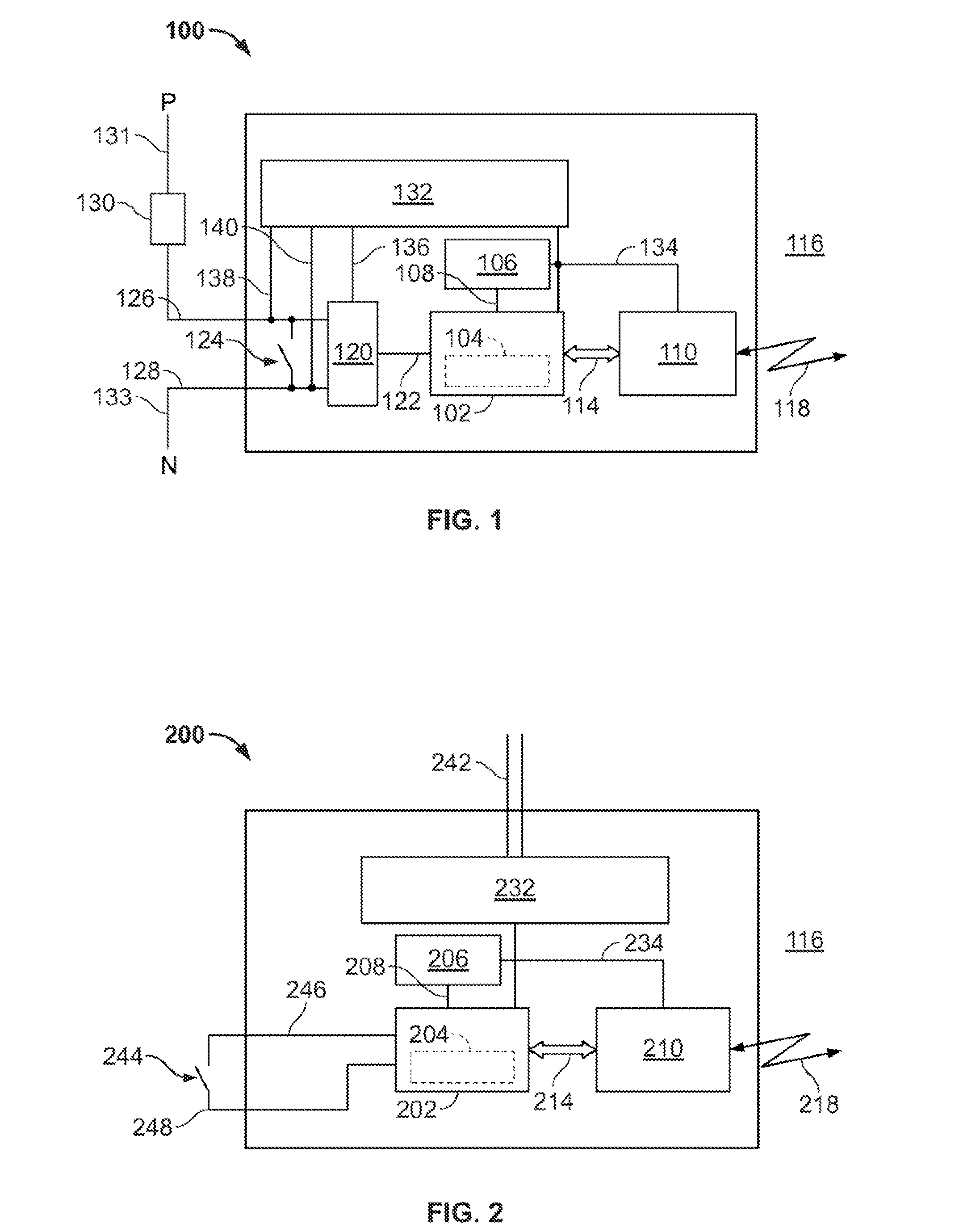
[0015]FIG. 1 is a block diagram of an exemplary actuator interface module 100. In the exemplary embodiment, module 100 is a circuit card. Alternatively, module 100 has any configuration that facilitates operation of module 100 as described herein. Module 100 includes at least one embedded controller 102. Controller 102 includes firmware 104. Firmware 104 is configured to implement at least a portion of the control logic (not shown) associated with module 100 and to facilitate interface communications. In the exemplary embodiment, the control logic is configured in a manner substantially similar to typical programmable logic controller (PLC) ladder logic using a programming language that includes, but is not limited to, at least a portion of Cimplicity® Machine Edition Logic Developer-PLC, commercially available from GE Fanuc Automation North America, Inc., Charlottesville, Va. Alternatively, the control logic is formed using any language in any configuration that facilitates operati...


PUM


Abstract

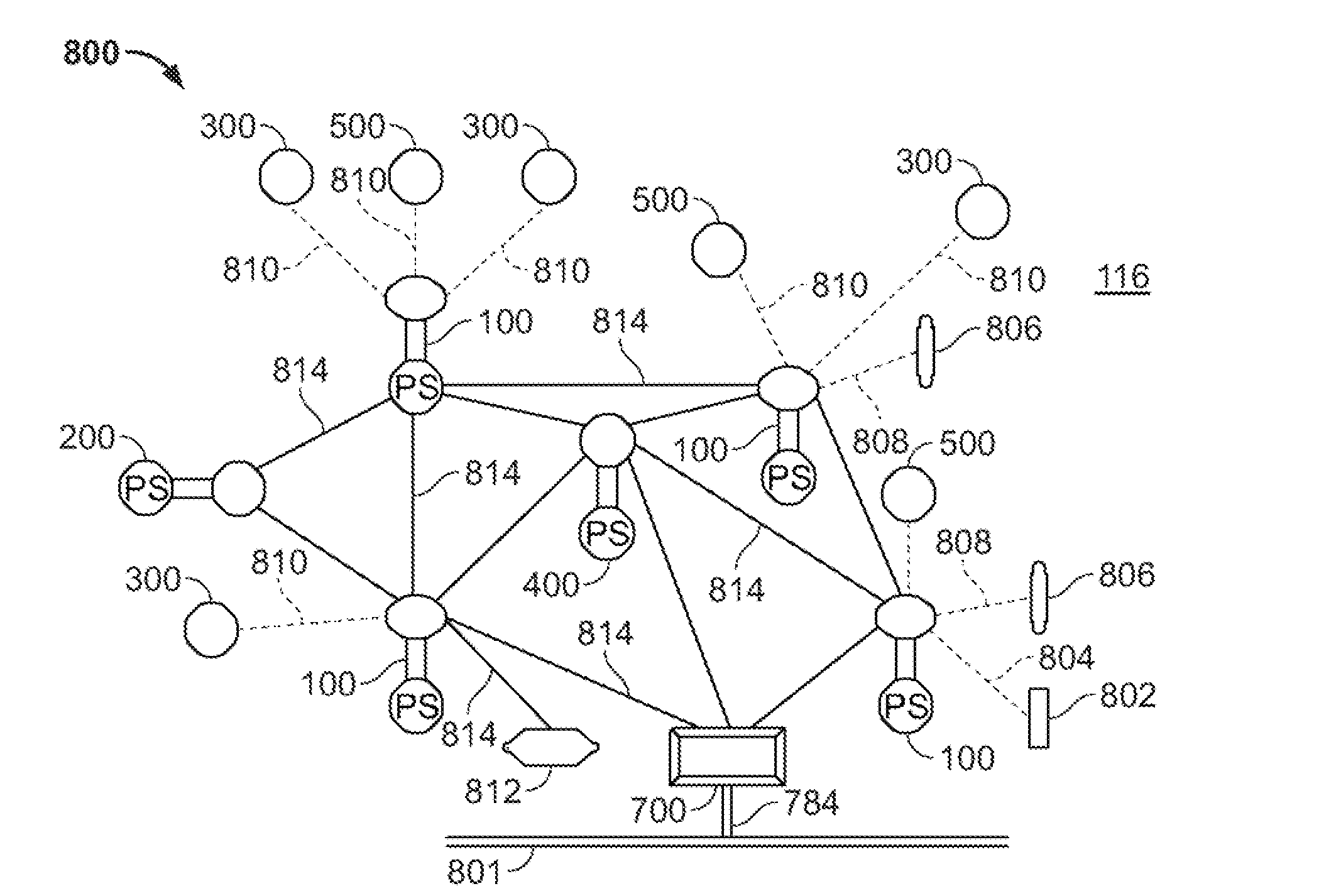
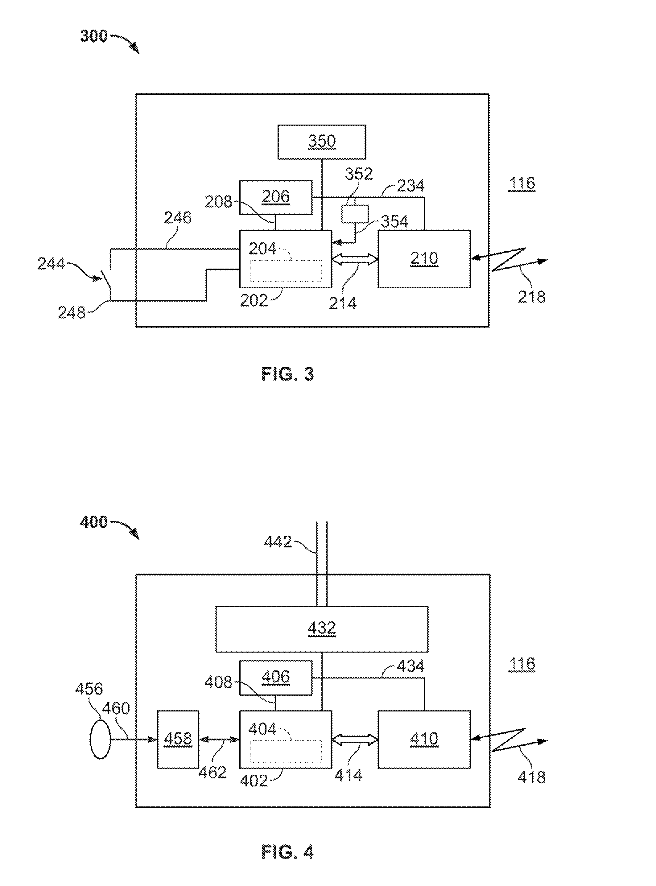
A method of distributing programmable control logic includes embedding substantially all of at least one programmable control logic scheme within at least one field device. A field device interface is embedded within the field device that includes firmware configured to facilitate execution of at least a portion of a programmable control logic scheme. The programmable control logic scheme is substantially contained within the firmware. The at least one field device forms at least a portion of a sensor actuator control network (SAC Net) that also includes at least one embedded actuator interface module and at least one embedded sensor interface module. Each of the modules include at least one of the field device interfaces embedded therein. The method also includes providing at least one logical input to the at least one programmable logic control scheme over at least a portion of the SAC Net.

Description

BACKGROUND OF THE INVENTION[0001]The present invention relates generally to logic control, and more particularly, to embedded programmable logic control and interface communication.[0002]Many known distributed programmable logic control systems include a plurality of programmable logic controllers (PLCs) or other processor-based configurations, or schemes, that include, but are not limited to, distributed control systems (DCSs). Typically, PLC-based distributed programmable logic control systems have both hardware and software components. Many of such PLC-based distributed control systems are used to manage independent parts of a factory floor, for example, to control a single component, small process or subsystem. PLCs are also used in expanded industrial control system applications to provide coordinated control of equipment, devices, systems and processes. PLCs generally comprise a central processing unit (CPU) and a plurality of input / output (I / O) modules having I / O connection t...

Claims


Application Information

Patent Timeline
IPC IPC(8): G06F15/177G06F15/16
CPCG05B19/0423G05B2219/25428G05B2219/25112
Inventor VARKU, SHRIKANT HANUMANTHA
Owner GE FANUC AUTOMATION NORTH AMERICA INC
Learn More