Control for UV water disinfection

a technology of control system and water disinfection, which is applied in the direction of fluorescence/phosphorescence, optical radiation measurement, and spectrometry/spectrometry/monochromator, etc., can solve the problems of wasting energy of lamps, unable to heat water, and unable to provide harmless microorganisms, so as to achieve the effect of full lamp output, reducing the time required to achieve full lamp output and sufficient heating

Inactive Publication Date: 2008-07-03
GENERAL ELECTRIC CO
View PDF21 Cites 22 Cited by
  • Summary
  • Abstract
  • Description
  • Claims
  • Application Information

AI Technical Summary

Benefits of technology

[0009]The time required to achieve full lamp output is minimized after the lamp has been in an off or low power state.
[0010]Sufficient heating is maintained in the UV lamp so that a starting voltage can be mo

Problems solved by technology

The UV radiation or light disrupts the DNA of the microorganisms which impacts on reproduction and thereby renders the microorganisms harmless.
It will be appreciated, however, that if water demand is infrequent and there are long periods of time where there is often standing water or low flow conditions, then the lamp is wasting energy.
Another problem with known systems is that a UV emitting lamp that is always “on” can unfortunately heat the water in the reactor/reservoir during low flow or static operation of the system.
Generally, the undesired heating impacts on cust

Method used


Image

  • Control for UV water disinfection
  • Control for UV water disinfection

Examples


Embodiment Construction

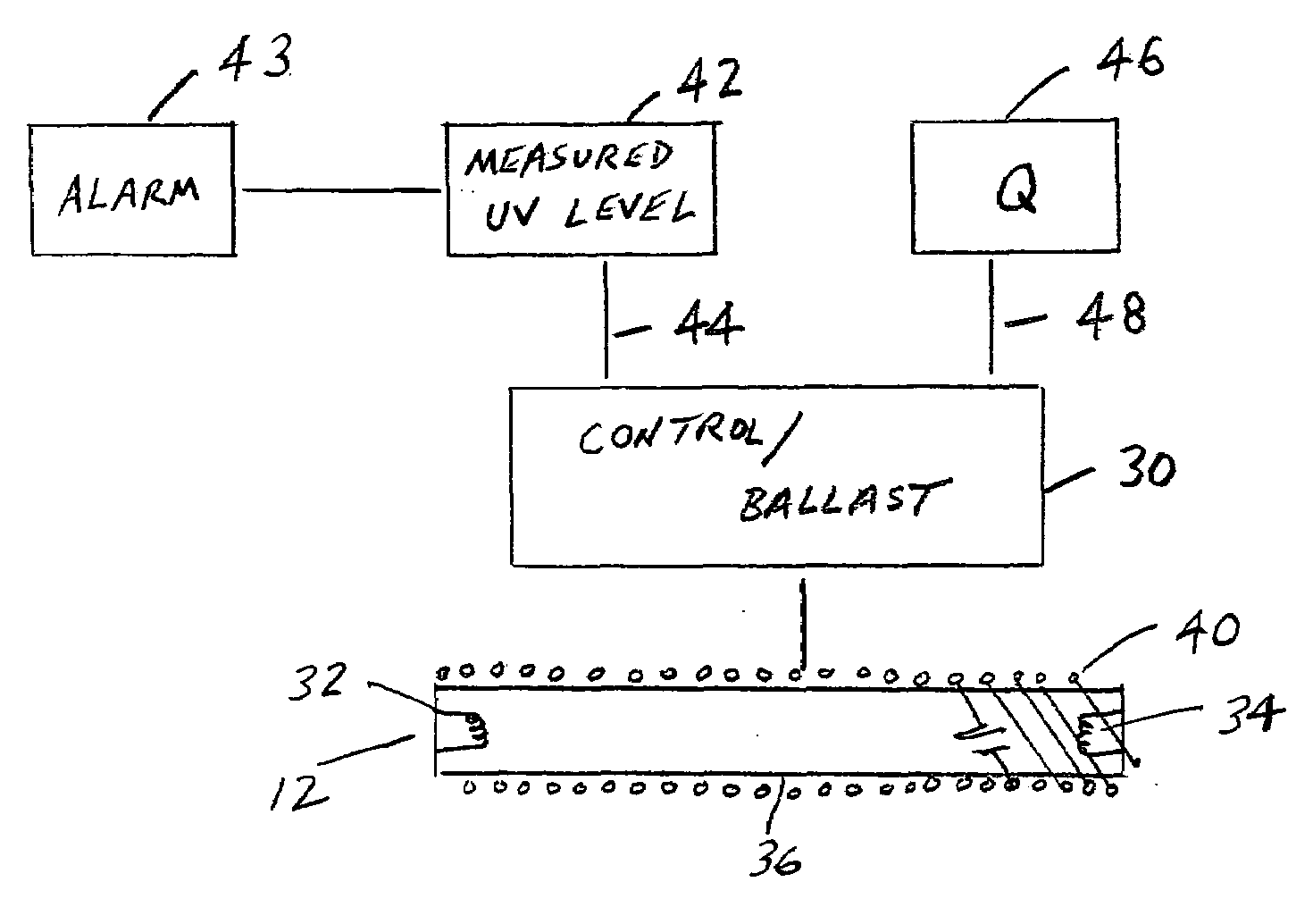
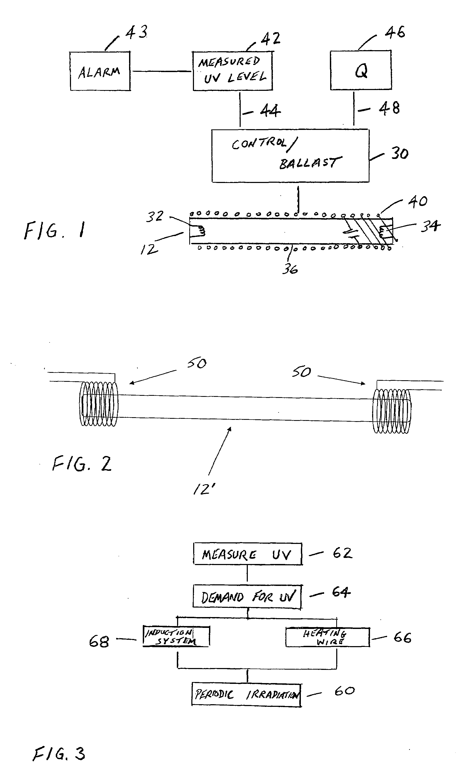
[0020]An ultraviolet light source water disinfection system is generally shown in FIG. 1. It includes a UV light source 12 received in a chamber, reactor, or reservoir 14 illustrated in dotted line. The lamp may be physically received within the chamber, or may emit light through a window into the chamber that holds a fluid, such as water. Inlet 16 supplies new water to the reservoir while outlet 18 provides UV dosed water for a downstream use (not shown). Since it is desired to provide for non-continuous or periodic operation of the lamp, rather than maintaining the lamp in an on condition, and in order to conserve energy, a ballast 30 controls operation of the lamp and provides the starting power necessary to strike an arc between the cathodes 32, 34 of the lamp. In a manner generally known in the art, the arc is established between the lamp cathodes, and a gas fill in lamp envelope 36 is excited and emits the desired wavelength of radiation or light. In the particular instance, t...


PUM

PropertyMeasurementUnit
Temperatureaaaaaaaaaa
Poweraaaaaaaaaa
Flow rateaaaaaaaaaa

Abstract

A UV light source water disinfection system includes a UV light source that is driven or controlled by a ballast. Improved start-up scenarios are provided by use of a separate heating wire around the lamp or employing an inductive-coupled system to provide initial high power requirements. The UV lamp is discontinuously operated in order to extend the life of the system, save energy, and periodically dose standing water to prevent regeneration of undesired microorganisms.

Description

BACKGROUND OF THE INVENTION[0001]This disclosure relates generally to a control system and more particularly to a ballast control for a light source treatment system of fluids such as an ultraviolet (UV) treatment of water commonly used in a home water treatment system.[0002]It is known in the art that UV light sources can be used to treat or disinfect / sterilize water such as described in commonly owned U.S. Pat. No. 6,057,917, the disclosure of which is incorporated herein by reference. Low-pressure mercury vapor discharge lamps, for example, have been widely used for many years for this purpose. Ultraviolet disinfection systems typically expose water to UV radiation (light) such that the radiation passes through the water and advantageously doses any microorganisms in the water. The UV radiation or light disrupts the DNA of the microorganisms which impacts on reproduction and thereby renders the microorganisms harmless. Of course, the intensity and duration of the UV exposure can ...

Claims


Application Information

Patent Timeline
IPC IPC(8): C02F1/32B01D21/30
CPCC02F1/008H05B41/36C02F2201/326C02F1/325
Inventor ALBRECHT, ANDYFISH, LARRYDUPLESSIS, SAMCHEN, TIMOTHY E.
Owner GENERAL ELECTRIC CO
Why Eureka
Try Eureka