Wind and water power generation device using a tiered monorail system

a technology of wind and water power generation and monorail, which is applied in the direction of vehicle energy devices, electric generator control, machines/engines, etc., can solve the problems of reducing the service life of monorail, unable to achieve the effect of delivering car derailment, and unable to meet the needs of the customer

Inactive Publication Date: 2008-07-03
LANDERS ENERGY INC
View PDF27 Cites 31 Cited by
  • Summary
  • Abstract
  • Description
  • Claims
  • Application Information

AI Technical Summary

Problems solved by technology

Further, all three suspension wheels are located inside the monorail, thereby rendering car derailment virtually impossible.
While the foregoing prior art references demonstrate improvement in the field of power generation, each of these prior art references have proven inadequate in several respects.
First, a system with a single monorail loop would require the monorail to withstand and resist tremendous cantilevering forces.
Irregular wind resource acting upon either a large upper or lower vane would demand that the single monorail be constructed with very heavy materials and the monorail would be susceptible to considerable fatigue.
This factor limits the size and overall height potential of the system and would reduce economies of scale.
For obvious reasons, this action would cause irregular ware on the guide wheels and the guide wheel's tracking area within the monorail.
Another concern is that the various working parts of the system are vulnerable to the environment.

Method used


Image

  • Wind and water power generation device using a tiered monorail system
  • Wind and water power generation device using a tiered monorail system
  • Wind and water power generation device using a tiered monorail system

Examples


Embodiment Construction

)

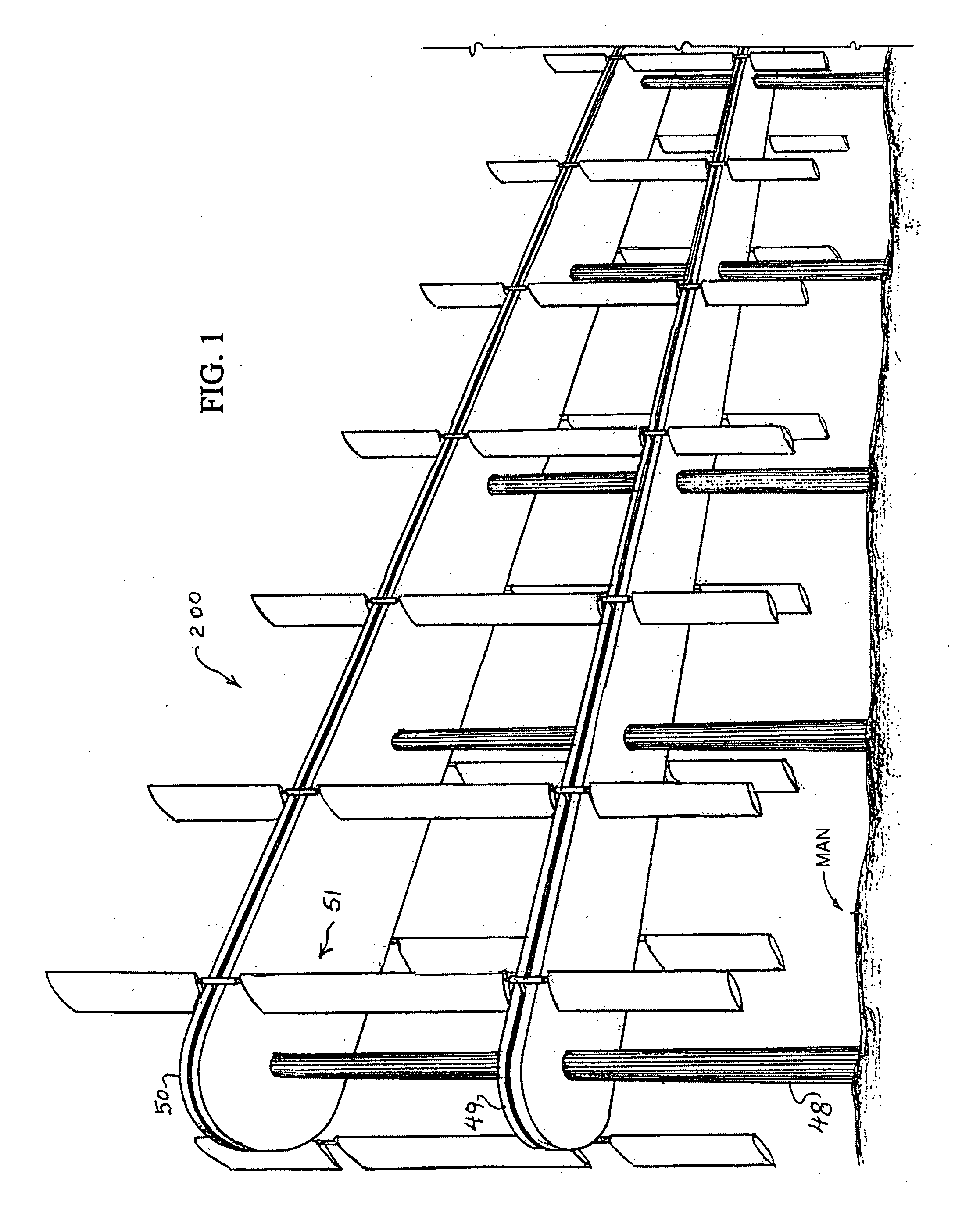
[0044]The presently preferred embodiments of the invention will be best understood by reference to the drawings, wherein like parts are designated with like numerals throughout.

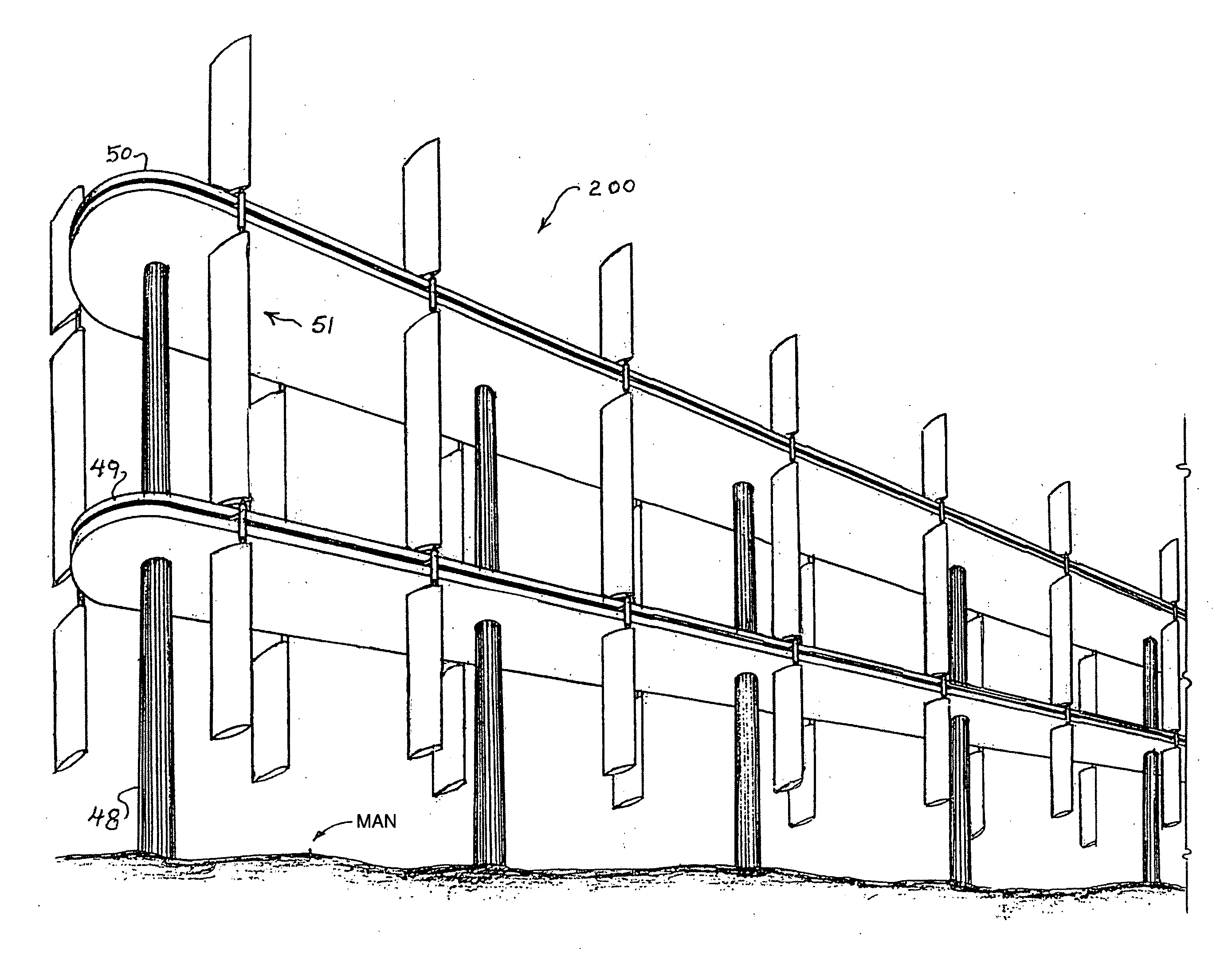
[0045]In FIG. 1 a power generation system 200 is shown. The power generation assembly includes a lower monorail 49 and an upper monorail 50 supported by a common pole support 48. Numerous vane assemblies 51 are shown. However, it is noted that the actual number of vane assemblies 51 used in each power generation assembly 49 and 50 may vary depending of need.

[0046]The vane assembly 51 consists of a frame 110 and at least one gang of vanes 52 and 54 positioned on the frame 110.

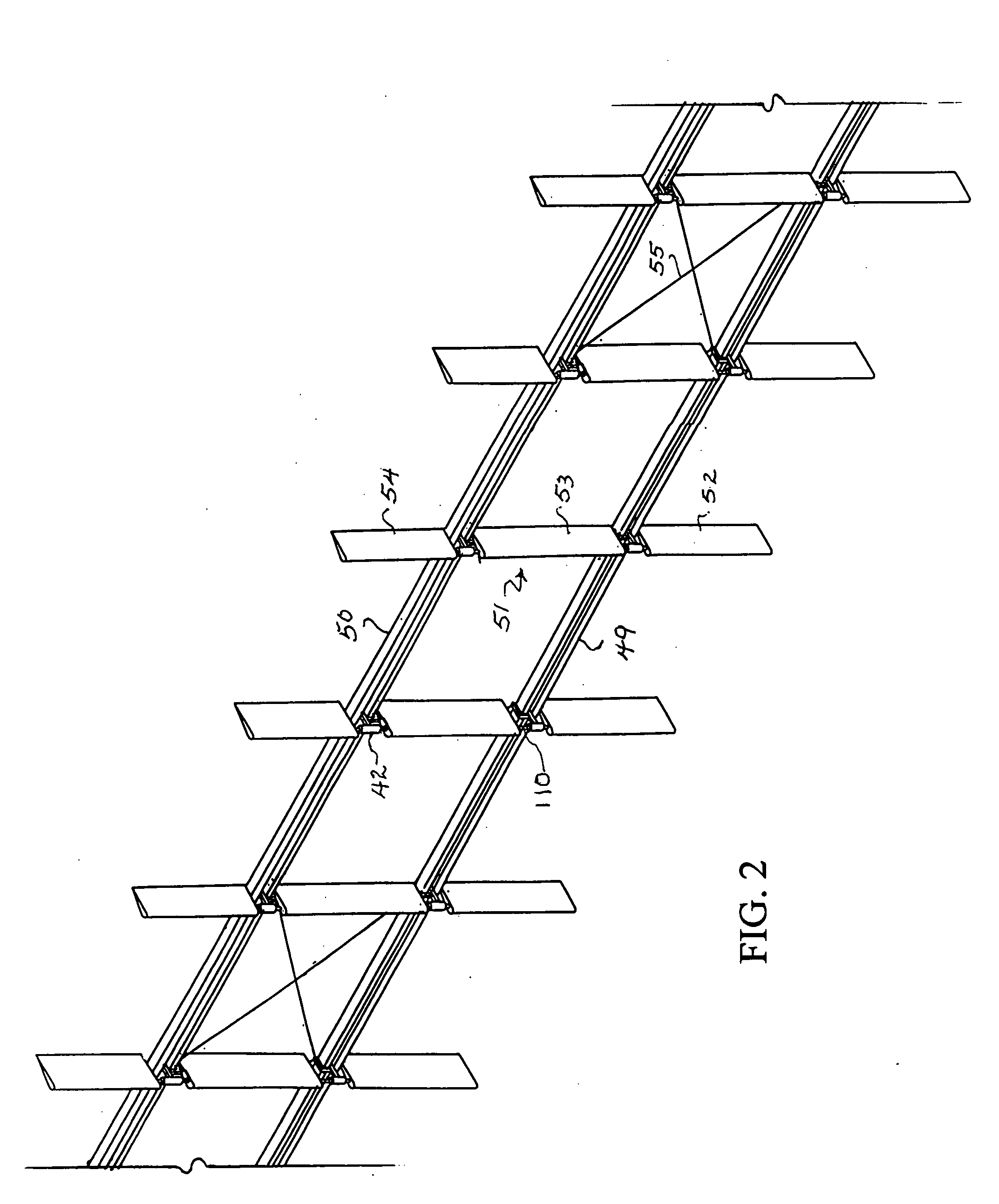
[0047]FIG. 2 shows sails 52, 53, and 54 that are coupled to a common frame which is pivotal in sleeve bearings 42 and are supported by a linkage portion 64. The linkage portion connects to car assembly 112 within monorail 49,50. Each sail assembly 51 is supported by guy cables to keep upper and lower car assemblies that share a common fr...


PUM


Abstract

A power generation assembly for use in generating electrical power from air or water currents includes a tiered rail system forming elongated loops, a vane assembly having a frame and at least one vain, and car assemblies sidably mounted to each rail, including linkage portions coupled to the frame of the vane assembly and a power-take-off arrangement includes an element that is operatively coupled to the car assembly and a drive wheel coupled to a generator and configured to take power off the moving car assembly by the drive wheels being rotated by the passing power-take-off element or a power-take-off system using a cable and clamps.

Description

THE FIELD OF THE INVENTION[0001]The present invention relates to a power generation assembly for use in generating electrical power from air or water currents, and more particularly to a dual monorail based conveyance system having low-mass car assemblies.BACKGROUND OF THE INVENTION[0002]In the last several decades wind power has grown to be a worldwide phenomenon with spectacular growth in the U.S. Recently, the Department of Energy has called for the development of larger and taller single unit wind machines to capture better wind resource at greater height. The DOE is encouraging the development of systems that will be more efficient in areas with somewhat lower wind speeds, particularly throughout the mid-western states where the resource is considered to be vast, and much development is expected.[0003]With the growing concerns about human caused global warming and instabilities in fossil fuel producing regions of the world, a growing number of people are voicing interest in the...

Claims


Application Information

Patent Timeline
Patent Type & Authority Applications(United States)
IPC IPC(8): B61B13/12B61B13/04B61D43/00
CPCF03B17/064F03D5/04F03D11/04F05B2210/16F05B2240/917Y02E10/728Y02E10/28Y02E10/70Y02E10/725Y02E10/727F05B2240/932F03D9/25F03D13/20F03D13/25Y02E10/20Y02E10/72
Inventor DAVISON, FRED E.DAVISON, GARY
Owner LANDERS ENERGY INC
Why Eureka
Try Eureka