Antenna structure and method for increasing its bandwidth

a technology of antenna and bandwidth, applied in the direction of antennas, antenna details, antenna feed intermediates, etc., can solve the problems of inability to process, difficulty in carrying, and limited antenna dimensions by wavelength and frequency, and achieve the effect of increasing the bandwidth and increasing the bandwidth thereo

Active Publication Date: 2008-07-03
DELTA ELECTRONICS INC
View PDF4 Cites 16 Cited by
  • Summary
  • Abstract
  • Description
  • Claims
  • Application Information

AI Technical Summary

Benefits of technology

[0008]It is therefore a first aspect of the present invention to provide an antenna structure and a method for increasing its bandwidth by providing a se

Problems solved by technology

As to an antenna structure, i.e. the present dipole antenna, it is not easy to carry because of its size.
Moreover, the dimensions of the antenna are limited by wavelength and frequency, and the available frequency is subject

Method used


Image

  • Antenna structure and method for increasing its bandwidth
  • Antenna structure and method for increasing its bandwidth
  • Antenna structure and method for increasing its bandwidth

Examples


Embodiment Construction

[0032]The present invention will now be described more specifically with reference to the following embodiment. It is to be noted that the following descriptions of preferred embodiment of this invention are presented herein for purposes of illustration and description only; it is not intended to be exhaustive or to be limited to the precise form disclosed.

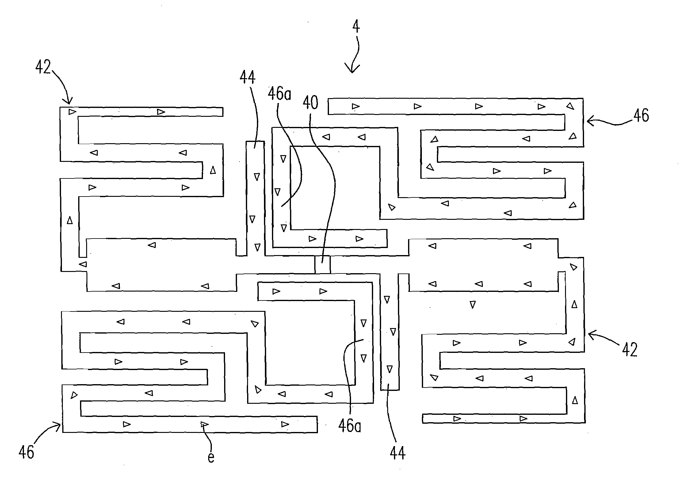
[0033]Please refer to FIG. 4, which is a schematic view showing an antenna structure and its current direction according to a preferred embodiment of the present invention. An antenna structure 4 includes a feeding portion 40 electrically connected to a first resonating element 42. Since the first resonating element 42 is a dipole antenna, the first resonating element 42 is symmetrically arranged with respect to the feeding portion 40. Further, a protruding portion 44 is near by the feeding portion 40. The protruding portion 44 is extended from a segment between the feeding portion 40 and the first resonating element 42 and is sym...


PUM


Abstract

An antenna structure and a method for increasing an antenna bandwidth are provided. The antenna structure includes a feeding portion, a first resonating element electrically connected to the feeding portion, a protruding portion electrically connected to the feeding portion, and a second resonating element coupled with the protruding portion.

Description

FIELD OF THE INVENTION[0001]The present invention is related to an antenna structure, and more particularly to an antenna structure with a wide bandwidth.BACKGROUND OF THE INVENTION[0002]As to an antenna structure, i.e. the present dipole antenna, it is not easy to carry because of its size. For the present radio frequency identification (RFID), it could be easy to carry with users by providing a conventional meander line antenna (MLA), which is folded at least once for reducing its size.[0003]Please refer to FIG. 1, which is a plan view showing a conventional meander line antenna. An inner-folding dipole antenna 1 includes a first dipole antenna 12 and a second dipole antenna 14. The first dipole antenna 12 and the second dipole antenna 14 are folded toward each other, respectively. Further, the first dipole antenna 12 and the second dipole antenna 14 are matched with a feeding point via a T-shaped network T. However, the length and the width of the inner-folding dipole antenna 1 a...

Claims


Application Information

Patent Timeline
IPC IPC(8): H01Q9/16H01Q1/36H01Q5/10
CPCH01Q1/36H01Q19/005H01Q9/26H01Q9/065
Inventor LU, JUNG CHIEHLI, HSIN CHUNG
Owner DELTA ELECTRONICS INC
Why Eureka
Try Eureka