Cursor control method and apparatus

Active Publication Date: 2008-07-03
PIXART IMAGING INC
View PDF10 Cites 14 Cited by
  • Summary
  • Abstract
  • Description
  • Claims
  • Application Information

AI Technical Summary

Benefits of technology

[0008]It is an object of the present invention to provide a cursor control method and apparatus, wherein a cursor on an image display is controlled by using an image sensor to detect the light of a predetermined spectrum generated by at least two reference points, wherein the rotation angle of the image sensor and the distance between the image sensor and the reference points are corrected during operation so as to increase the accuracy of cursor control.
[0009]It is another object of the present invention to provide a cursor control method and apparatus, wherein locations of at least two reference points which can generate light of a predetermined spectrum can be determined by a user during operation so as to increase the operating convenience.
[0011]It is a further object of the present invention to provide a cursor control method and apparatus, wherein a cursor on an image display is controlled by using an image sensor to detect the light of a predetermined spectrum generated by at least two reference points, wherein the image sensor can detect the light only from the reference points so as to simplify the image recognition.
[0012]In order to obtain the above objects, the cursor control method of the present invention is for controlling the movement of a cursor on an image display and includes the following steps: providing at least two reference points for generating light of a predetermined spectrum and defining a predetermined area; providing an image sensor for pointing inside the predetermined area; receiving the light of the predetermined spectrum by the image sensor to form a digital image; identifying positions and shapes of the images of the reference points on the digital image to form a first parameter; performing distance and angle compensations on the first parameter; moving the aiming point of the image sensor inside the predetermined area to form a second parameter; and calculating a displacement of the images of the reference points on the digital image according to the compensated first parameter and the second parameter so as to accordingly control the movement of the cursor.

Problems solved by technology

However in practical use, although this method can be applied to any types of image display for playing shooting games with the photographic pointer positioning device without being limited by the type of image display, the image recognition process of the display area detected by video camera is still complicated due to containing pictures shown on the image display.
Furthermore, the video camera has to detect the whole display area no matter which point is aimed by the photographic pointer positioning device; therefore the method further has the problem of needing a video camera with large viewing angle.
However in practical use, when the hand-held device is used by a user to detect an image area, image positions will be obviously affected according to different distances between the hand-held device and the objects to be captured and different rotation angles of the hand-held device during photographing.
If the distance and rotation angle variations are not corrected, errors may be generated during the calculation of the position differential.
Furthermore, since the images detected by the hand-held device include other objects, e.g. pictures shown on a display screen, image recognition is complicated.

Method used


Image

  • Cursor control method and apparatus
  • Cursor control method and apparatus
  • Cursor control method and apparatus

Examples


Embodiment Construction

[0026]It should be noticed that, wherever possible, the same reference numbers will be used throughout the drawings to refer to the same or like parts.

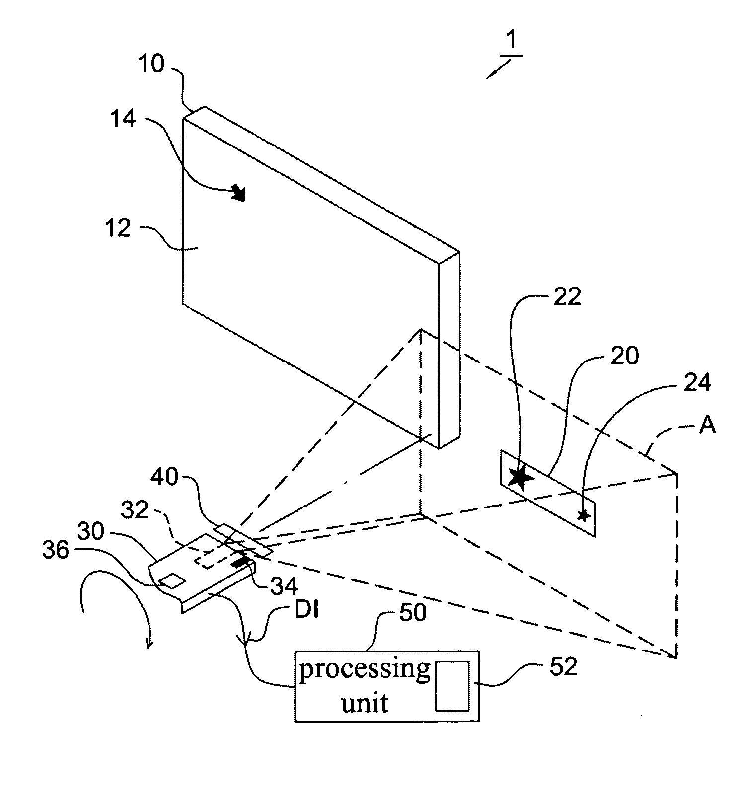
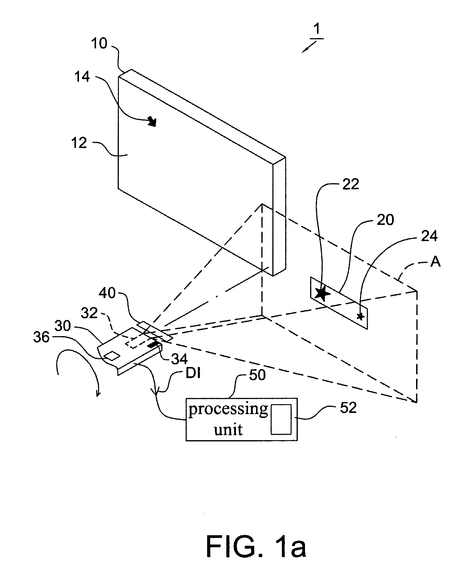
[0027]Referring to FIG. 1a, it schematically shows the cursor control apparatus 1 according to the first embodiment of the present invention. The cursor control apparatus 1 includes an image display 10, at least two reference points 22 and 24, a remote controller 30, an image sensor 32, an optical filter 40 and a processing unit 50. Embodiments of the image display 10 include a computer screen, a television, a game machine and any apparatus for displaying images. Preferably, function setting and tuning of the image display 10 are implemented by means of a user interface, and a cursor 14 is shown on the screen 12 of the image display 10 for a user to perform interactive control, e.g. volume control, sound effects control and color control etc, on the user interface through the cursor 14 so as to humanize the operation of the image disp...


PUM


Abstract

A cursor control method for controlling a cursor on an image display includes: providing at least two reference points for generating light of a predetermined spectrum and defining a predetermined area; providing an image sensor pointing inside the predetermined area; receiving the light of the predetermined spectrum by the image sensor to form a digital image; identifying positions and shapes of the images of the reference points on the digital image to form a first parameter; performing distance and angle compensations on the first parameter; moving the aiming point of the image sensor inside the predetermined area to form a second parameter; and calculating an displacement of the images of the reference points on the digital image according to the compensated first and second parameters so as to accordingly control the cursor. The present invention further provides a cursor control apparatus.

Description

CROSS REFERENCE TO RELATED APPLICATION[0001]This application claims the priority benefit of Taiwan Patent Application Serial Number 095149408, filed on Dec. 28, 2006, the full disclosure of which is incorporated herein by reference.BACKGROUND OF THE INVENTION[0002]1. Field of the Invention[0003]This invention generally relates to a cursor control method and an apparatus, and more particularly to a method and an apparatus for controlling a user interactive cursor shown on an image display.[0004]2. Description of the Related Art[0005]A conventional pointer positioning device and method is disclosed in Taiwan Patent No. 588258 and entitled “A photographic pointer positioning device”. It utilizes a photographic pointer positioning device to process the image out-line so as to obtain coordinate values of four corners of display area, and then obtain the coordinate values corresponding to the aiming point of a video camera by coordinate calculating process so as to replace the method of o...

Claims


Application Information

Patent Timeline
IPC IPC(8): H04N5/44G06F3/033G09G5/08A63F13/20A63F13/213A63F13/235G06F3/0346
CPCG06F3/0317G06F3/0325H04N2005/4432H04N5/4403G06F3/0346H04N21/42204H04N21/42206H04N21/42222
Inventor CHAO, TZU YIWU, MENG TSUNGCHEN, HSIN CHIALIN, CHIH HSINTSAI, CHANG CHEHUANG, CHAO CHIENLEE, YI FANG
Owner PIXART IMAGING INC
Why Eureka
Try Eureka