Monitoring system, monitoring method, and program

a monitoring system and monitoring method technology, applied in the field of monitoring systems and monitoring methods, can solve the problems of not being able to inspect the monitor image quickly, unable to quickly detect the motion of the monitor, and a large data amount of the monitor image generated when a motion is detected, so as to increase the image capturing resolution, increase the image capturing frame rate, and increase the data amount of the monitor image generated

Inactive Publication Date: 2008-07-03
FUJIFILM CORP
View PDF8 Cites 9 Cited by
  • Summary
  • Abstract
  • Description
  • Claims
  • Application Information

AI Technical Summary

Benefits of technology

[0006]However, the image capturing apparatus disclosed in Patent Document 1 captures an image at a low frame rate while no motion has been detected, and increases the image capturing frame rate or increases the image capturing resolution when a motion having a predetermined value or more has been detected from the image at the low frame rate under image capturing. Therefore, according to the image capturing apparatus recited in Japanese Patent Application Pub

Problems solved by technology

Therefore, according to the image capturing apparatus recited in Japanese Patent Application Publication No. 2004-200989, the data amount of a monitor image generated when a motion has been detected will be extremely large.
When such a monitor image is attempted to be transmitted

Method used


Image

  • Monitoring system, monitoring method, and program
  • Monitoring system, monitoring method, and program
  • Monitoring system, monitoring method, and program

Examples


Embodiment Construction

[0031]The invention will now be described based on the preferred embodiments, which do not intend to limit the scope of the present invention, but exemplify the invention. All of the features and the combinations thereof described in the embodiment are not necessarily essential to the invention.

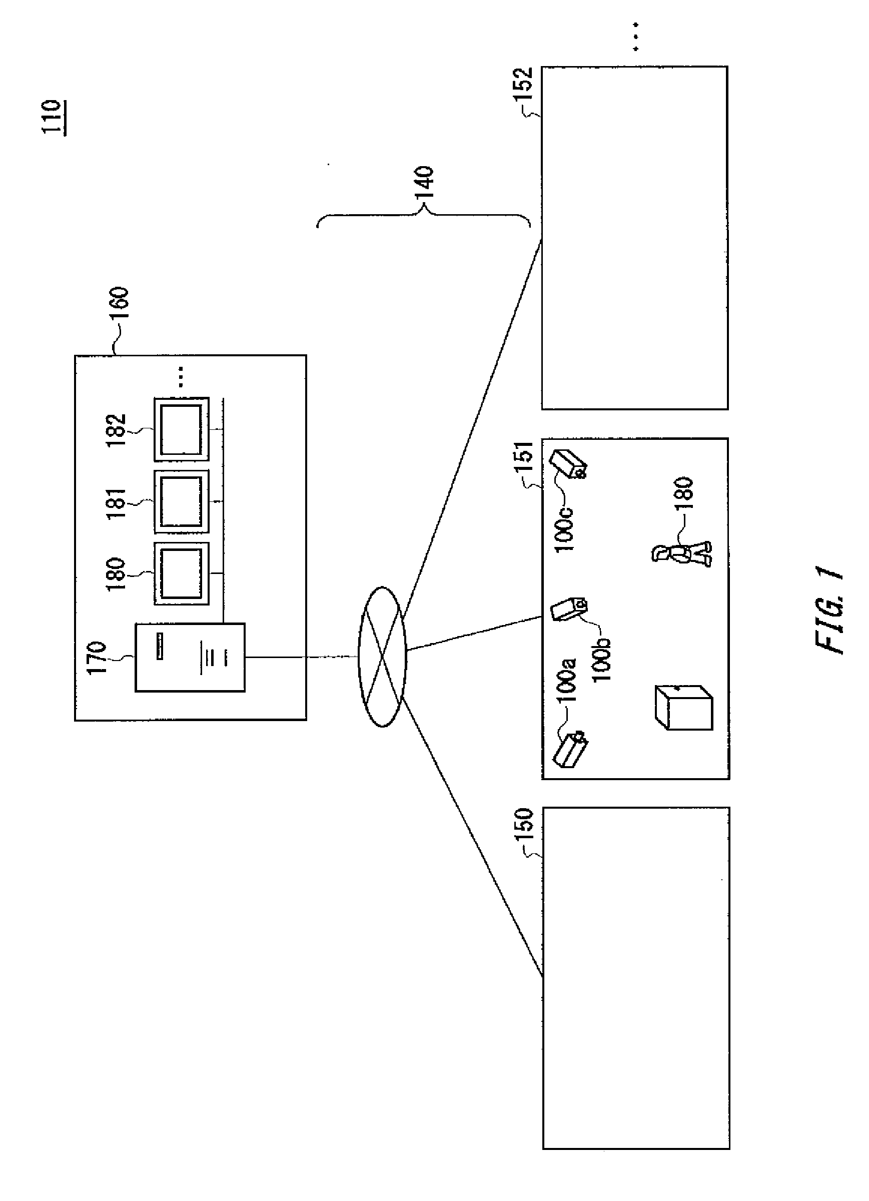
[0032]FIG. 1 shows one example of an environment in which a monitoring system 110 is used according to one embodiment. The monitoring system 110 includes a plurality of image capturing apparatuses 100a-c, a transmission path 140, a server 170, and a plurality of display apparatuses 180, 181, 182, . . . . The server 170 and the plurality of display apparatuses 180, 181, 182, . . . are provided in a monitoring room 160 remote from the monitor regions 150, 151, 152, . . . . Note that the image capturing apparatuses 100a-c are provided with respect to the plurality of monitor regions 150, 151, 152, . . . respectively, for capturing images of the plurality of monitor regions 150, 151, 152, . . . ,...


PUM


Abstract

A monitoring system includes: an image capturing section capturing a motion image of a monitor region; a condition storing section storing a condition of an object to be extracted from the motion image; a matching judging section judging whether an object that matches the condition exists in the motion image; an object region identifying section identifying an object region including the object, if the matching judging section judges positively; an output section outputting an image of the object region, if the matching judging section judges positively; an image retaining section retaining an image of a region other than the object region, if the matching judging section judges positively; and an output control section controlling the output section to output the image of the region, if the image of the region is judged to be transmitted, after the image retaining section retained the image of the region.

Description

CROSS REFERENCE TO RELATED APPLICATION[0001]The present application claims priority from Japanese Patent Applications No. 2006-353192 filed on Dec. 27, 2006, and No. 2007-323646 filed on Dec. 14, 2007 the contents of which are incorporated herein by reference.BACKGROUND[0002]1. Technical Field[0003]The present invention relates to a monitoring system, a monitoring method, and a program. In particular, the present invention relates to a monitoring system, a monitoring method, and a program for the monitoring system, which are for pursuing monitoring using an image.[0004]2. Description of the Related Art[0005]Such an image capturing apparatus is known to reduce the frame rate for image capturing by the image capturing section by relatively lengthening the period for the synchronization signal to be supplied to the image capturing section while the motion vector detected by the motion image compression section is less than a predetermined value, and to increase the frame rate for image...

Claims


Application Information

Patent Timeline
IPC IPC(8): G06K9/00
CPCH04N19/20H04N19/51
Inventor NOGUCHI, YUKINORITAKAMORI, TETSUYA
Owner FUJIFILM CORP
Why Eureka
Try Eureka