System and method for a subscriber-powered network element

Inactive Publication Date: 2008-07-03
SOTO ALEXANDER I +1
View PDF8 Cites 182 Cited by
  • Summary
  • Abstract
  • Description
  • Claims
  • Application Information

AI Technical Summary

Benefits of technology

[0012]According to the present invention, techniques related to local powering of a network element or drop site by a subscriber or customer remote device or gateway are provided. Certain advantages and/or benefits may be achieved using the present invention. For example, the present invention has the advantage of being free of any requirement for add

Problems solved by technology

Twisted copper wire does not support high bandwidths over a great distance and while coax cable does a better job, it too has reach and bandwidth limitations.
One major problem with bringing fiber cable within a short distance of a customer location is the added burden of maintaining the multitude of optical to copper drop sites.
Optical fiber itself is not capable of carrying the electricity to power these drop sites.
This creates a challenge in planning, distributing and deployment of electricity to power the drop sites' energy needs.
However, increased voltages raise craft safety issues.
Furthermore, there is the 24-hour a day cost of supplying electricity to the power network, as well as regu

Method used


Image

  • System and method for a subscriber-powered network element
  • System and method for a subscriber-powered network element
  • System and method for a subscriber-powered network element

Examples


Embodiment Construction

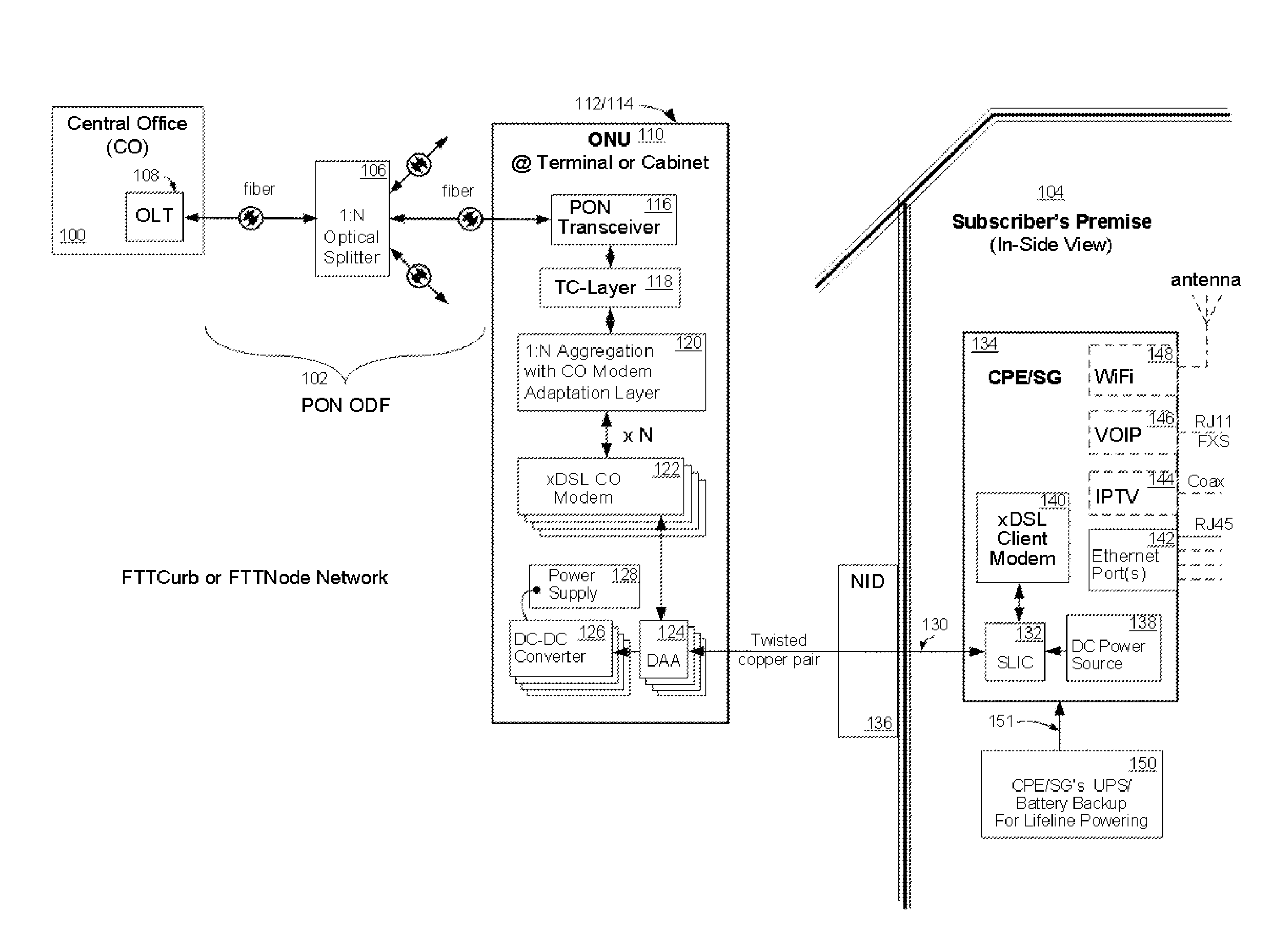
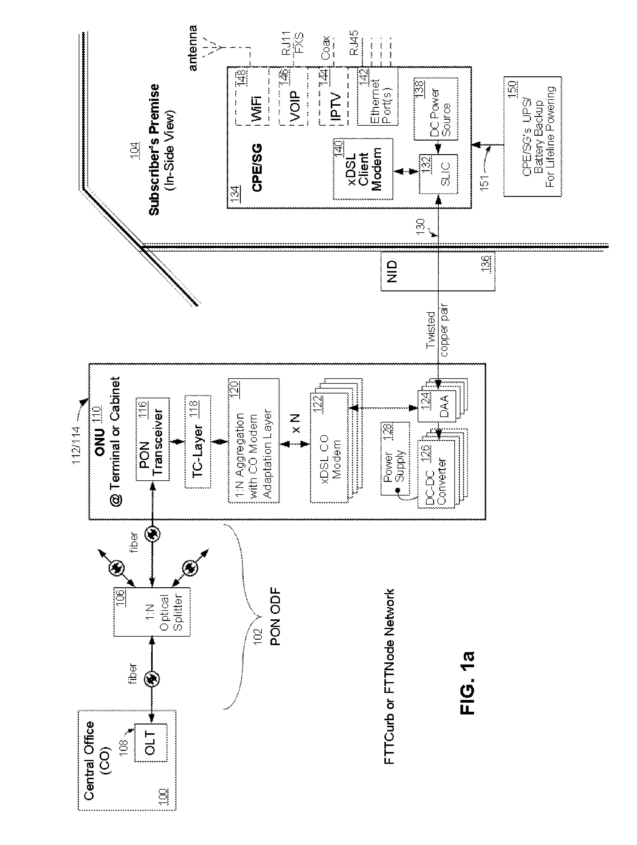
[0037]Referring now to FIG. 1a, wherein like reference numerals designate identical or corresponding parts throughout the several views and embodiments and wherein cascading boxes below a part designates a plurality of such parts, an exemplary embodiments of an electrical power architecture for a fiber optic communication network is shown incorporating a subscriber-powered network element, according to the present invention. A FTTC or FTTN network using a PON connects a central office (CO) 100 at the head end of a passive optical distribution fabric (ODF) 102 to a subscriber premise 104. The subscriber premise 104 can be residential homes and / or commercial buildings. The passive ODF 102 is comprised of a plurality of passive optical splitters 106 and connectors (not shown). An Optical Line Terminal (OLT) 108, which is located at the CO 100, acts as a central transmission point and an overall controlling device for the network. The OLT 108 is in communication through the ODF 102 with...


PUM


Abstract

A system for powering a network element of a fiber optic communication network. When communication data is transferred between a central office (CO) and a subscriber gateway using a network element to convert optical to electrical (O-E) and electrical to optical (E-O) signals between a fiber from the central office and copper wires or coax cable from the subscriber gateway, techniques related to local powering of a network element or drop site by a subscriber or customer remote device or gateway are provided. Certain advantages and/or benefits are achieved using the present invention, such as freedom from any requirement for additional meter installations or meter connection charges. Additionally the system is free of monthly meter charges and does not require a separate power network.

Description

CROSS-REFERENCES TO RELATED APPLICATIONS[0001]This application is filed under 37 C.F.R. §1.53(b) as a continuation-in-part of patent application Ser. No. 11 / 369,512, which was filed on Mar. 01, 2006 under 37 C.F.R. §1.53(b) claiming the benefit under 35 U.S.C. 119(e) of the provisional Patent Application No. 60 / 657,511 filed on Mar. 01, 2005, now abandoned.FIELD OF THE INVENTION[0002]The invention relates generally to fiber optic communication networks, more specifically to the powering architecture of broadband access networks and particularly to subscriber powering of broadband access networks.BACKGROUND OF THE INVENTION[0003]With increasing customer demand for transmitting and receiving increasingly greater amounts of information, telecommunication and cable companies are being pushed to upgrade their communication network infrastructures. In order to supply more information in the form of video, audio and telephony at higher rates, higher bandwidth communication network upgrades...

Claims


Application Information

Patent Timeline
IPC IPC(8): H04B10/00
CPCH04M19/08H04B10/808
Inventor SOTO, ALEXANDER I.SOTO, WALTER G.
Owner SOTO ALEXANDER I
Why Eureka
Try Eureka