
Eureka
For R&D, Eureka makes reading and utilizing patents & technical documents easy.
Eureka AIR
Designed for self-driven R&D workflows. Generate viable solutions, solve complex R&D challenges, empower your innovation with AI.

Eureka Materials
Designed for material experts only. Revolutionize your material R&D, from search, analyze, to developing new materials.

TechResearch
Generate reliable direction feasibility study reports for your R&D in just a few steps.

TechSeek
Discover and master advanced knowledge NOW. Basics, ideas, possibilities, all at once.

TechMind
As an expert in R&D Theories, TechMind can generates customized viable solutions instantly.

TechRisk
Analyze your overall solution with one click, know your potential R&D risks in advance.

TechMonitor
Get weekly tech updates, stay abreast of the latest tech innovations and key insights.
Charging device and image forming apparatus
- Summary
- Abstract
- Description
- Claims
- Application Information
AI Technical Summary
Benefits of technology
Problems solved by technology
Method used
Image

Examples
second embodiment
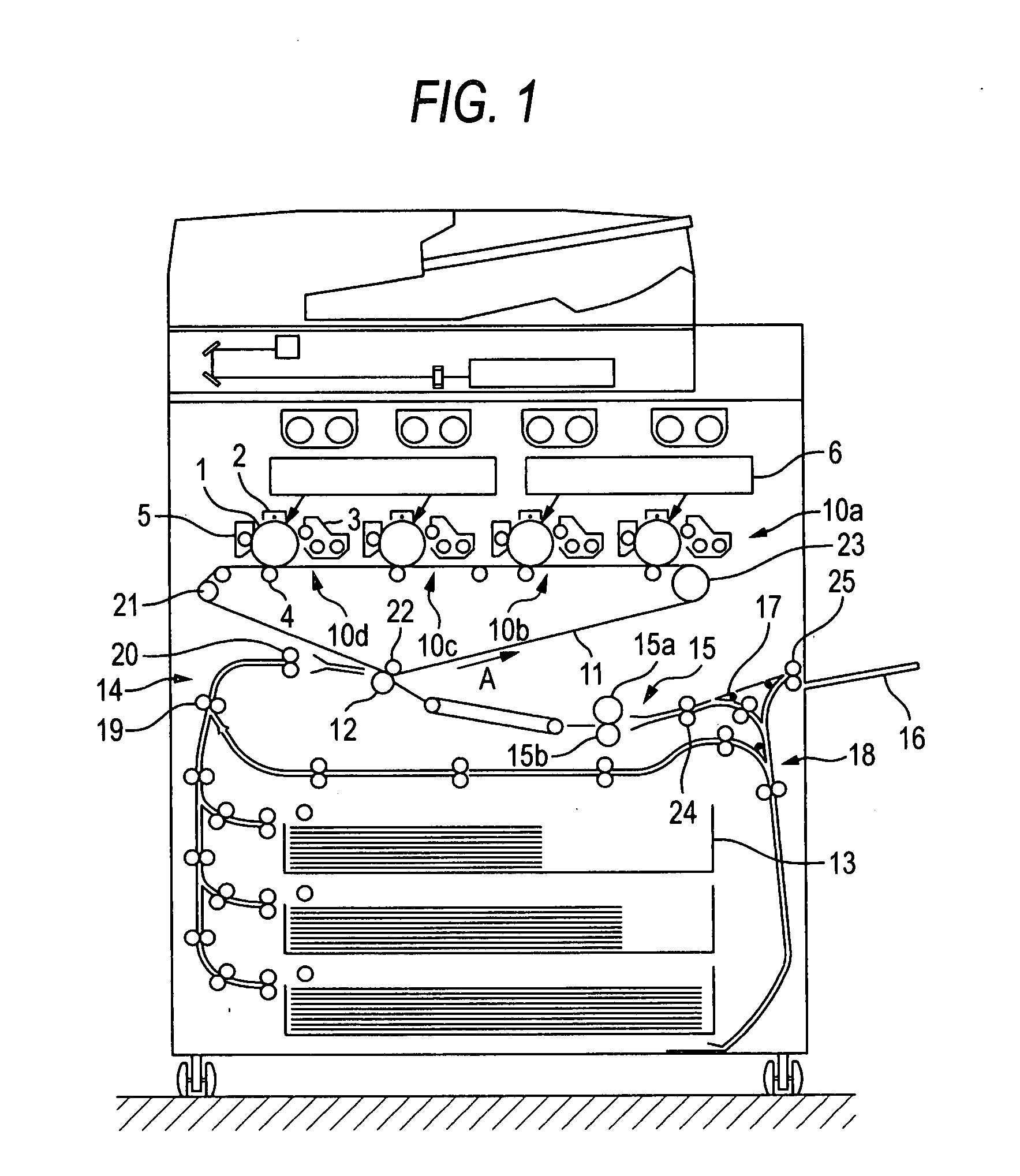
[0070]Next, the charging device according to the invention, which can be used in the image forming apparatus shown in FIG. 1, is described below.
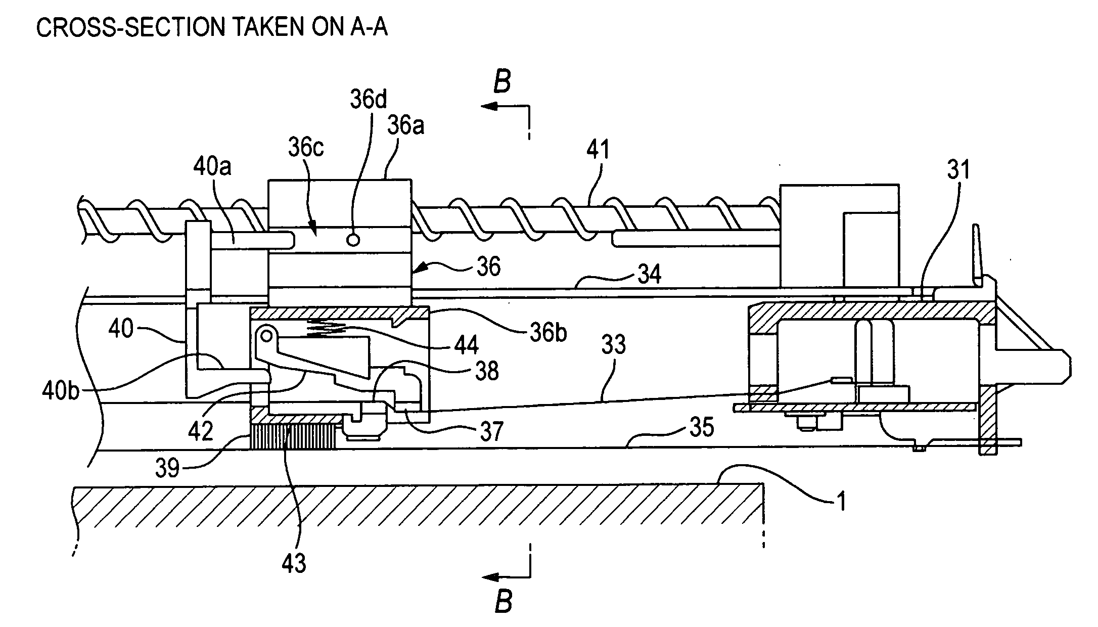
[0071]FIGS. 11A and 11B are cross-sectional views illustrating this charging device which can be used in the image forming apparatus according to the second embodiment of the invention. FIG. 11A illustrates a cross-section of the charging device, which is taken in a direction perpendicular to the axis line of the electrode wire stretched in the direction of width of the circumferential surface of the photoreceptor drum 1. FIG. 11B illustrates a cross-section of the charging device, which is taken in a direction parallel to the axis line of the electrode wire, that is, taken on line A-A in FIG. 11A. FIG. 12 illustrates a cross-section of the charging device taken on line B-B in FIG. 11A.
[0072]This charging device has a front end member 51 and a rear end member 52, which are fixed and supported, an electrode wire 53 stretched therebetween, a ...
third embodiment
[0079]FIG. 15 is a cross-sectional view illustrating the charging apparatus according to the invention.
[0080]This charging device has end members 71 and 72, an electrode wire 73, a shield case 74, a screw member (not shown), and a cleaning unit, similarly to the charging device shown in FIGS. 11A to 14. Similarly, the cleaning unit has a support member 76, a first pad 77, a second pad (not shown), and a movement member 80. Incidentally, in this changing device differing from the charging device shown in FIGS. 11A and 11B in the length of a part of the movement member 80, which is projected from the support member 76, and in the mounting angle of each of a first arm 83 and a second arm 86 fixed to a support shaft 82.
[0081]In the charging device according to the third embodiment, as shown in FIG. 15A, in a state in which the movement member 80 is protruded rearwardly from the support member 76, the first pad 77 is pushed against the electrode wire 73. Also, the support member 76 moves...
fourth embodiment
[0082]FIGS. 16A and 16B are a cross-sectional view illustrating the charging device according to the invention, and a schematic view illustrating a mechanism configured to control the contact pressure of each of the pads to the electrode wire.
[0083]This charging device has an end member 91, an electrode wire 93, a shield case 94, a screw member 95, and a cleaning unit, similarly to the charging device shown in FIGS. 11A to 14. Similarly, the cleaning unit has a support member 96, a first pad 97, a second pad 98, and a movement member 99. Incidentally, in this changing device according to the fourth embodiment, a guide member 94a, which is an example of the guide member, is provided along the direction of the electrode wire 93 inside a side surface portion of the shield case 94. This guide member 94a is provided by being inclined so as to gradually approach the photoreceptor drum 1 from the front side to the rear side. On the other hand, at an end portion of a second arm 103 protrudi...
PUM
 Abstract
Description
Claims
Application Information
 - R&D Engineer
- R&D Manager
- IP Professional
- Industry Leading Data Capabilities
- Powerful AI technology
- Patent DNA Extraction
Browse by: Latest US Patents, China's latest patents, Technical Efficacy Thesaurus, Application Domain, Technology Topic, Popular Technical Reports.
© 2024 PatSnap. All rights reserved.Legal|Privacy policy|Modern Slavery Act Transparency Statement|Sitemap|About US| Contact US: help@patsnap.com