Instrument for modular orthopaedic prosthesis

Active Publication Date: 2008-07-03
DEPUY SYNTHES PROD INC
View PDF17 Cites 4 Cited by
  • Summary
  • Abstract
  • Description
  • Claims
  • Application Information

AI Technical Summary

Benefits of technology

[0024]The technical advantages of the present invention further include the ability to allow for a less invasive procedure than would be possible if one needed to position the trial head with the hand. For example, according to another aspect of the present invention, a tool assembly is provided for use in a trial reduction in a shoulder joint arthroplasty. The tool assembly includes a driver for cooperation with the fastener to secure the first component to the second component of a humeral trial stem assembly. A handle is also provided with the tool assembly and includes a first feature for permitting the driver to pass through the handle and a second feature orientably connecting the handle to the articulating humeral head. Thus, the present invention provides for an ability to provide for a less invasive procedure than would be possible if positioning the trial head with the hand.
[0025]The technical advantages of the present invention further include the ability to manipulate the head of a humeral stem assembly without having to visually see the head. With the limited space in the surgical site, the surgeon can easily manipulate the position of the trial head. For example, according to another aspect of the present invention, a tool assembly is provided including a driver for cooperation with the fastener to secure the distal trial stem with the proximal neck. The assembly also includes a handle having a first feature in the form of a cylindrical opening to permit the driver to pass through the handle and a second feature in the form of a protrusion which cooperates with a feature on the articulating humeral head to orientably connect the handle to the articulating humeral head. Thus, the present invention provides for the ability to manipulate the humeral head without having to see the head. Such a device permits for a less invasive procedure as the incision may be smaller in that the vision of the head is not required.
[0026]The technical advantages of the present invention further include the ability to not need to hold a slippery humeral head. For example, according to yet another aspect of the present invention, a tool assembly for use in humeral joint arthroplasty is provided. The tool assembly includes a driver for cooperation with the fastener to secure the distal humeral stem to the articulating neck component. The tool assembly further includes a handle having a first feature in the form of a longitudinal opening to permit the driver to pass through the handle and a second feature for connecting the handle to the articulating trial component. Thus, the present invention provides the ability to utilize a handle with a feature to hold a feature on the articulating humeral head so that the articulating humeral head does not need to be held manually by the surgeon

Problems solved by technology

Doing so with the surgeon's hands is very difficult because of limited space to maneuver and due to the slippery conditions of the trial head.
Such torque may otherwise cause a pro

Method used


Image

  • Instrument for modular orthopaedic prosthesis
  • Instrument for modular orthopaedic prosthesis
  • Instrument for modular orthopaedic prosthesis

Examples


Embodiment Construction

[0054]Embodiments of the present invention and the advantages thereof are best understood by referring to the following descriptions and drawings, wherein like numerals are used for like and corresponding parts of the drawings.

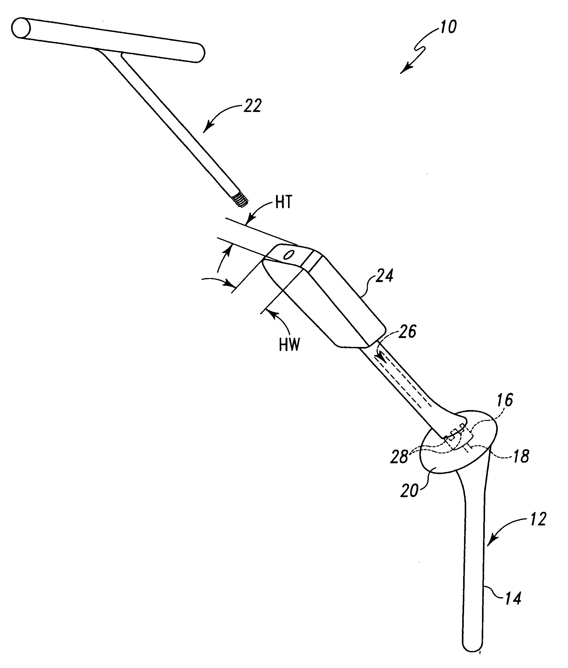
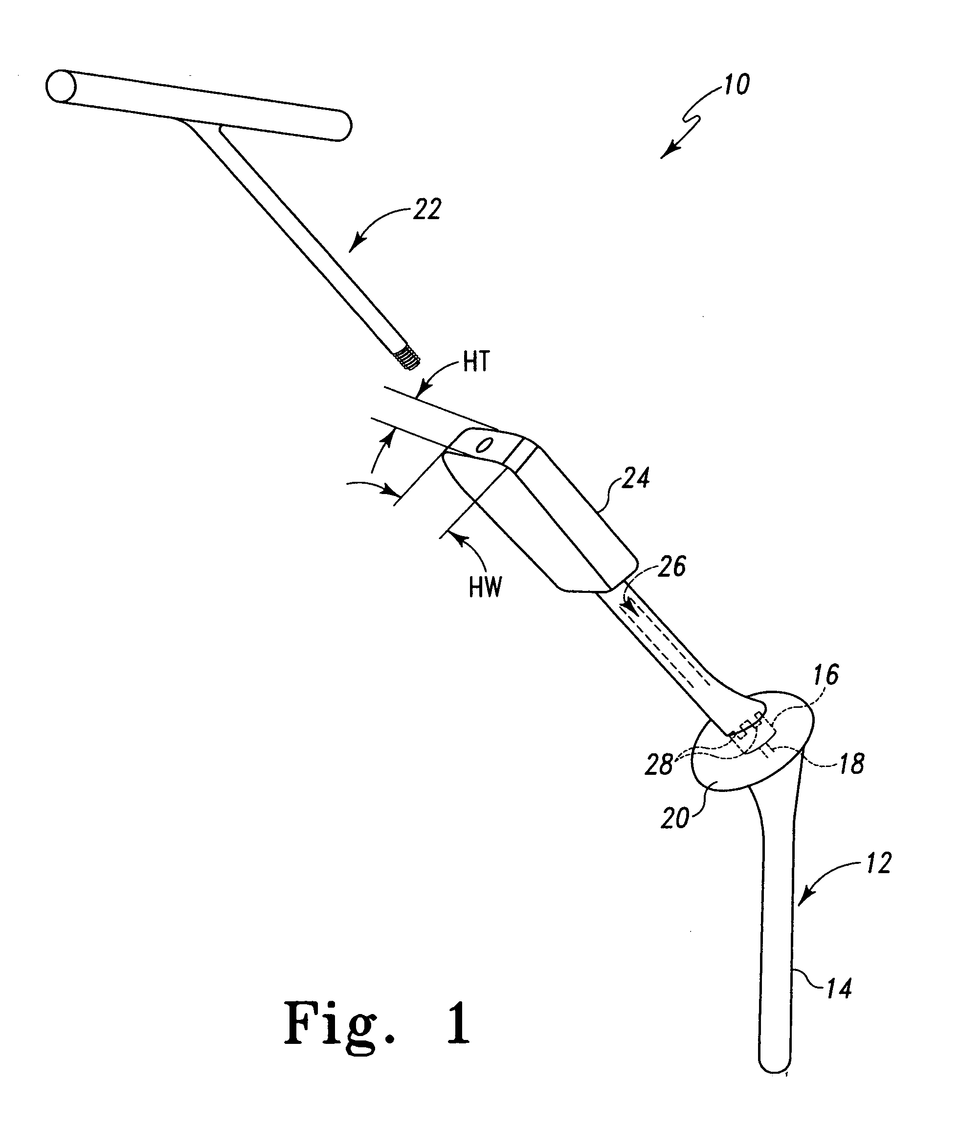
[0055]According to the present invention and referring now to FIG. 1, a kit 10 for use in performing a trial reduction in joint arthroplasty is shown. The kit 10 includes a trial stem assembly 12 including a first component 14. The first component 14 may, as shown in FIG. 1, be in the form of a distal trial stem. The distal trial stem 14 may be a distal trial stem for a humerus as part of a shoulder prosthesis or may be a distal trial stem for a hip prosthesis in the form of a distal trial stem for a femur. It should be appreciated that the distal trial stem may be fitted into any long bone.

[0056]The trial stem assembly 12 further includes a second component 16 which is selectively moveable with respect to the first component 14. The second component 16 may be...


PUM


Abstract

A kit for use in performing a trail reduction in joint arthroplasty is provided. The kit includes a trail stem assembly including a first component, a second component selectably moveable with respect to the first component, and a fastener for securing the first component to the second component. The kit also includes an articulating trial component removeably fixedly secured to the trail stem assembly and a driver for cooperation with the fastener to secure the first component to the second component. The kit also includes a handle. The handle has a first feature for permitting the driver to pass through the handle and a second feature for orientably connecting the handle to the articulating trial component.

Description

TECHNICAL FIELD OF THE INVENTION[0001]The present invention relates generally to the field of orthopaedics, and more particularly, to an instrument for use in arthroplasty.BACKGROUND OF THE INVENTION[0002]The present invention relates to implantable articles and methods of for implanting such articles. More particularly the invention relates to a bone prosthesis, prosthesis trial, instrument and method for implanting the same.[0003]There are known to exist many designs for and methods for implanting implantable articles, such as bone prostheses. Such bone prostheses include components of artificial joints, such as elbows, hips, knees and shoulders.[0004]One such implantable prosthesis is a shoulder prosthesis. During the life time of a patient, it may be necessary to perform a total shoulder replacement procedure on a patient as a result of, for example, disease or trauma, for example disease from osteoarthritis or rheumatoid arthritis. Currently, most implantable shoulder prosthese...

Claims


Application Information

Patent Timeline
IPC IPC(8): A61B17/60
CPCA61F2/40A61F2/4014A61F2/4059A61F2/4637A61F2/4684A61F2002/4668A61F2002/4029A61F2002/4037A61F2002/4044A61F2002/4062A61F2002/4018
Inventor KLOTZ, CONRAD L.BAUGHMAN, CHAD L.WILLIMAN, DANIEL J.
Owner DEPUY SYNTHES PROD INC
Why Eureka
Try Eureka