
Wide path leaf blower attachment

a leaf blower and wide path technology, applied in the field of leaf blower attachments, can solve the problems of physical challenge and tiring for some users

Inactive Publication Date: 2008-07-10
DISANTO RICHARD JOHN
View PDF6 Cites 5 Cited by
  • Summary
  • Abstract
  • Description
  • Claims
  • Application Information

AI Technical Summary

Benefits of technology

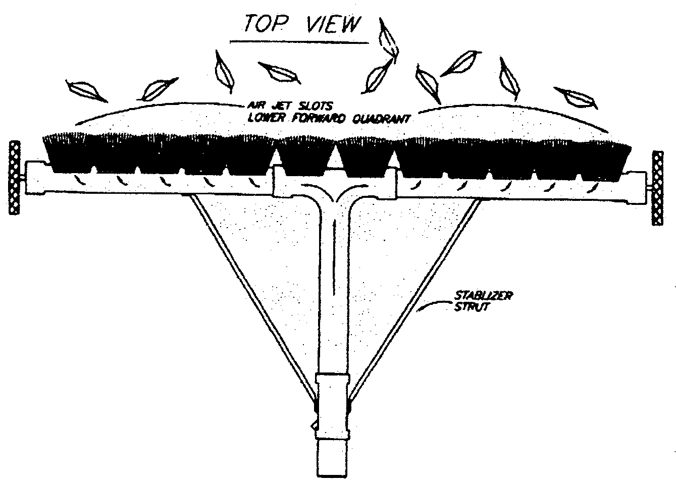
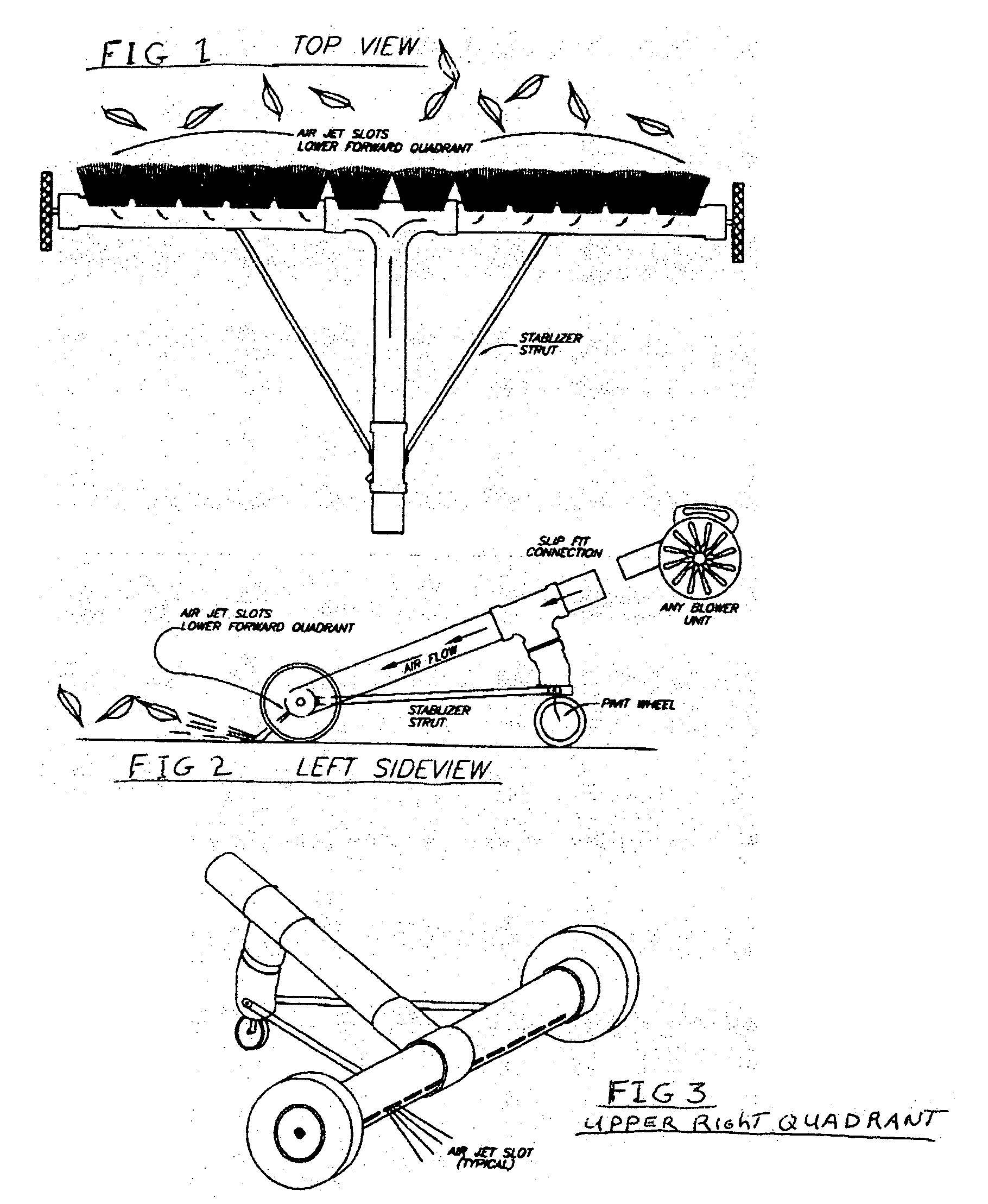
[0003]The objective of the claimed invention is to offer an attachment / apparatus which, when used in conjunction with nearly any make / model of commercially available leaf blowers, will provide a simple, effortless method of clearing a six foot wide path of leaves from driveways, walkways and lawns. This objective was accomplished by inserting / mounting the discharge end of a leaf blower into the inlet end of the assembled attachment. The air provided by the blower is channeled through the 3″ I.D. tube to a horizontal manifold of like size and material which provides an evenly distributed flow of high-velocity air to clear the leaves. The horizontal manifold tube is supported by an eight inch diameter wheel fixed at each end. The inlet tube is supported by a vertical tube of like size and material which incorporates, at the bottom end cap, a five inch diameter wheel which can pivot / swivel 360 degrees and supports the full weight of the blower and provides easy steering of the entire unit. Two ½ inch metal stabilizer bars provide rigidity from the support tube to the horizontal manifold tube. Because all materials are thin wall plastic tubes supported by plastic wheels, the result is a lightweight, easy to maneuver unit which allows the user to clear a substantial area of leaves with minimum effort.

Problems solved by technology

This can be both tiring and physically challenging to some users, especially the very young or the very old customer.

Method used


Image

  • Wide path leaf blower attachment
  • Wide path leaf blower attachment

Examples


Embodiment Construction

[0007]The proof of concept model of the wide path leaf blower attachment is shown in FIGS. 1, 2 and 3 wherein a electric or gasoline powered is inserted into the supply tube and channeled downward into a horizontal air manifold which displaces the high velocity air through a series of discharge air slots located on the lower front quadrant of the manifold. This action enables the user to clear a six foot wide path of leaves by simply pushing the combined unit straight ahead without the need to either swing the leaf blower from side to side or carry any weight of the leaf blower. The aforementioned air manifold section is supported by two main wheels, one mounted on each end of the manifold tube. Supporting the weight of the leaf blower is a near vertical tube of like material which has, mounted at the bottom, a 360 degree swivel / pivot wheel which, in addition to supporting the total weight, provides the steering of the combined unit by the user.

[0008]The claimed invention as shown i...


PUM


Abstract

This is a leaf blower attachment which can be used with nearly any hand-held or back-pack type of leaf blower commonly on the market today, either electric or gas powered. It is designed for the purpose of clearing a six foot wide path of leaves from driveways, walkways or lawns by simply pushing the assembled unit (leaf blower and attachment) straight ahead with not much more effort than pushing a grocery shopping cart. This is accomplished by connecting nearly any make / brand / model of available market leaf blowers to my invention by either inserting the blower discharge tube directly into the attachment, or by means of utilizing a specific manufacturer's adapter fitting, if necessary. Because the attachment carries the entire weight of the blower head, it can be used efficiently, safely and easily by both the very young (as tested by an eight year old boy) and the elderly (as tested by an 81 year old woman). It eliminates both the need to swing a leaf blower from side to side, or carry the weight of a leaf blower. In the event someone who is handicapped has the desire to be self-sufficient and would like to clear leaves by themselves, my invention provides a motorized version which can be powered by two 6-12 volt variable speed / reversible electric motors controlled by using a dual radio controller. This optional equipment is commonly available (i.e.: radio controlled toys) and can be easily combined with my invention.

Description

BACKGROUND OF INVENTION[0001]The claimed invention relates to a leaf blower attachment used to clear a six foot wide path of leaves from driveways, walkways and lawns without the need to swing a blower from side to side or carry the weight of a leaf blower. It comprises an electrical or gasoline powered air blower, commonly used in yard work, in combination with a series of assembled tubes, fittings and wheels. This combination is used to blow a wide path of leaves with a minimum of effort. The wide path attachment, in effect, transfers the present method of a single air flow source to a manifold system which displaces the air flow across a wide area without any appreciable loss in velocity.PRIOR ART[0002]The most commonly used method of clearing leaves is to hand-carry a leaf blower and use a side to side swinging motion to achieve the goal. This can be both tiring and physically challenging to some users, especially the very young or the very old customer. This invention eliminate...

Claims


Application Information

Patent Timeline
Patent Type & Authority Applications(United States)
IPC IPC(8): A01D7/00
CPCA01G1/125A01G20/47
Inventor DISANTO, RICHARD JOHN
Owner DISANTO RICHARD JOHN
Learn More