
Carpentry marking tool

a marking tool and carpentry technology, applied in the field of carpentry marking tools, can solve the problems of difficult uniform positioning or use of prior art measuring devices such as tape measures and rulers with positioning slides, and difficult to accurately measure such short and precise measurements, and achieve the effect of quick and very accurate positioning of lines or marks, easy use and inexpensive production

Inactive Publication Date: 2008-07-10
WILLIAMS GARY E
View PDF22 Cites 3 Cited by
  • Summary
  • Abstract
  • Description
  • Claims
  • Application Information

AI Technical Summary

Benefits of technology

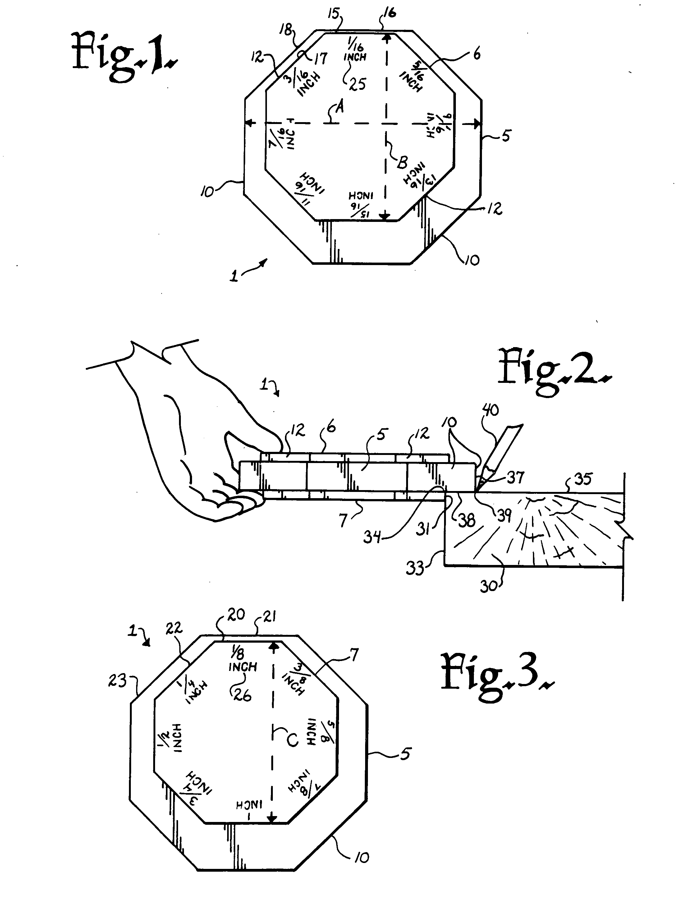
[0011]Therefore, the objects of the invention are: to provide a carpentry marking tool that allows a user to quickly and very accurately position a line or mark a desired distance from an edge of a board or other structural component; to provide such a tool having a center or base and smaller top and bottom portions all having a uniform polyhedral shape wherein the top and bottom portions are offset with respect to the base and each other, such that each edge of the top and bottom portions is a specific and different distance from a corresponding base edge; to provide such a tool that is easy to use, inexpensive to produce and especially well adapted for the intended use thereof.
[0012]Other objects and advantages of this invention will become apparent from the following description taken in conjunction with the accompanying drawings wherein are set forth, by way of illustration and example, certain embodiments of this invention.
[0013]The drawings constitute a part of this specification and include exemplary embodiments of the present invention and illustrate various objects and features thereof.

Problems solved by technology

It is often difficult to accurately measure such short and precise measurements with a tape measure or rule and when using such a device, multiple marks must be made and a line drawn between them to provide a guide line.
Further, prior art measuring devices, such as tape measures and rulers with positioning slides, are often difficult to uniformly position or to use in getting highly repetitive and accurate measurements.

Method used


Image

  • Carpentry marking tool
  • Carpentry marking tool
  • Carpentry marking tool

Examples


Embodiment Construction

[0018]As required, detailed embodiments of the present invention are disclosed herein; however, it is to be understood that the disclosed embodiments are merely exemplary of the invention, which may be embodied in various forms. Therefore, specific structural and functional details disclosed herein are not to be interpreted as limiting, but merely as a basis for the claims and as a representative basis for teaching one skilled in the art to variously employ the present invention in virtually any appropriately detailed structure.

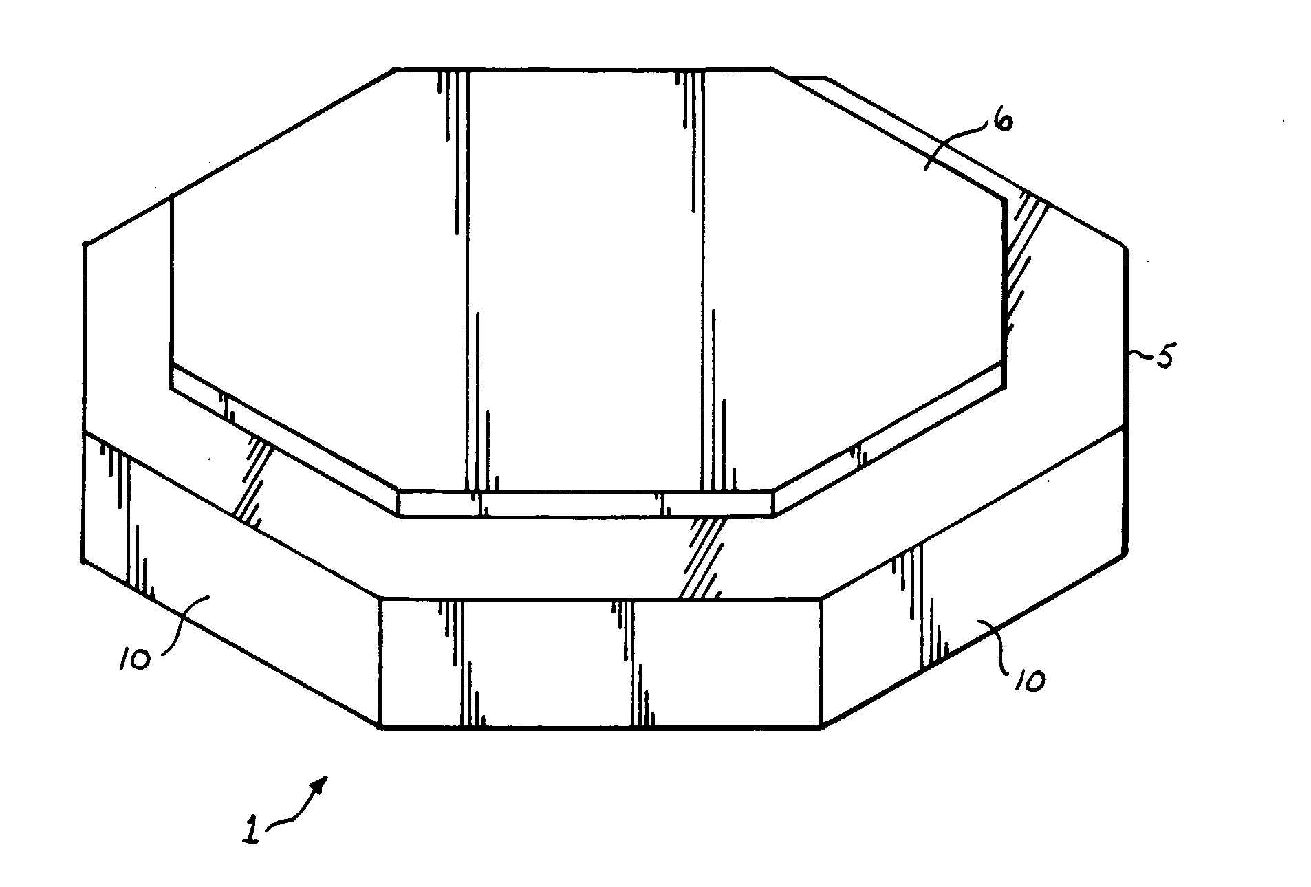
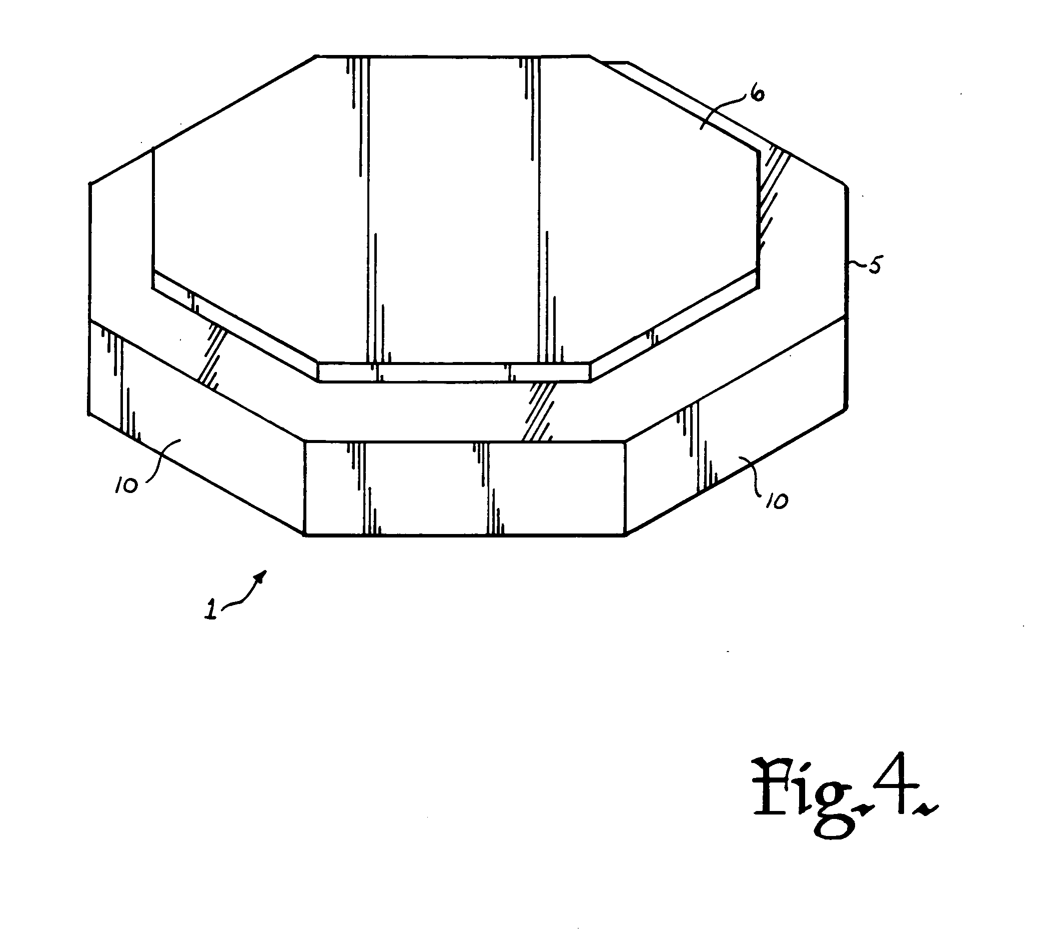
[0019]Shown in the drawings is a marking tool generally designated by the reference numeral 1. The tool 1 indicates a central, middle or base portion 5, a top portion 6 and a bottom portion 7.

[0020]The base portion 5 is of uniform height throughout and has an octagonal cross section (in a horizontal plane) that has eight uniform side surfaces 10. The base portion 5 has a maximum width that is indicated by dimensional arrow identified by the letter A.

[0021]The...


PUM


Abstract

A marking tool comprising bottom, base and top polyhedral shaped portions integrally joined such that the top and bottom portions are skewed with respect to each other and the base, such that a plurality of selected spaced distances are defined between adjacent walls of the top and bottom portions relative to walls of the base portion.

Description

CROSS REFERENCE TO RELATED APPLICATIONS[0001]This application claims the benefit of U.S. Provisional Application No. 60 / 879,125 filed Jan. 8, 2007.BACKGROUND OF THE INVENTION[0002]The present invention is directed to a tool for allowing a carpenter or other craftsmen to quickly and accurately mark distances from an edge and, in particular to a marking block having a base with a polyhedral shape and smaller top and bottom portions having the same polyhedral shape but of a smaller size and offset with respect to the base.[0003]Carpenters, such as cabinet makers, must make frequent and accurate dimensional measurements to provide a guide as to where to make a cut with a saw, where to drill, where to place pulls or handles and the like. Many of these measurements are in the range of one sixteenth of an inch to one inch in one sixteenth with increments in the American system using inches or in one tenth of a centimeter increments in systems using the metric system.[0004]It is often diffi...

Claims


Application Information

Patent Timeline
Patent Type & Authority Applications(United States)
IPC IPC(8): B43L7/033
CPCB25H7/02B43L13/028B43L7/033
Inventor WILLIAMS, GARY E.
Owner WILLIAMS GARY E
Learn More