
Hydraulic Fluid Cooling Apparatus and Method

Inactive Publication Date: 2008-07-10
TITAN RES & INNOVATIONS
View PDF4 Cites 2 Cited by
  • Summary
  • Abstract
  • Description
  • Claims
  • Application Information

AI Technical Summary

Benefits of technology

[0015]The fluid cooler, positioned between the charge pump and the main pump is able to provide the main pump with a continuous source of sufficiently cooled fluid under conditions of overload for extended periods in relatively high ambient temperatures such as, for example, temperatures up to 52° C. Thus, the hydraulic fluid is able to be cooled within the main closed circuit loop of the apparatus which includes the fluid cooler and the charge and main pumps, and does not need to be cooled off-line.
[0019]Preferably, the pressure of the hydraulic fluid between the charge pump and the main pump is relatively constant. This allows for more reliable performance of a suitably designed fluid cooler.

Problems solved by technology

The ability of these drive apparatus to operate under sustained loads in relatively high ambient temperatures such as 22° C. and above has traditionally been limited by their ability to adequately cool the hydraulic fluid which circulates through them.
A problem with conventional closed-loop hydrostatic drive apparatus of the type described above is that the hydraulic fluid retained in the apparatus which has already passed through the high pressure section of the hydraulic circuit of the apparatus once and not discharged through motor case drains, internal lubrication circuits and the like, must then pass through that section again with the retained heat from the previous pass.
As this happens, the ability of the hydraulic apparatus to perform to expectations is greatly diminished.
This increased temperature of the hydraulic fluid diminishes the performance of the apparatus and can only be reduced by stopping the operation of the apparatus for a sufficient period of time or by operating the apparatus for a relatively prolonged period of time at a load demand which is well below the 100 kilowatts which the apparatus is designed to transmit.
In high power and high load applications, the tank capacity which is required to provide adequate cooling is usually so large that it is not feasible to have a tank of the required capacity.

Method used


Image

  • Hydraulic Fluid Cooling Apparatus and Method
  • Hydraulic Fluid Cooling Apparatus and Method

Examples


Embodiment Construction

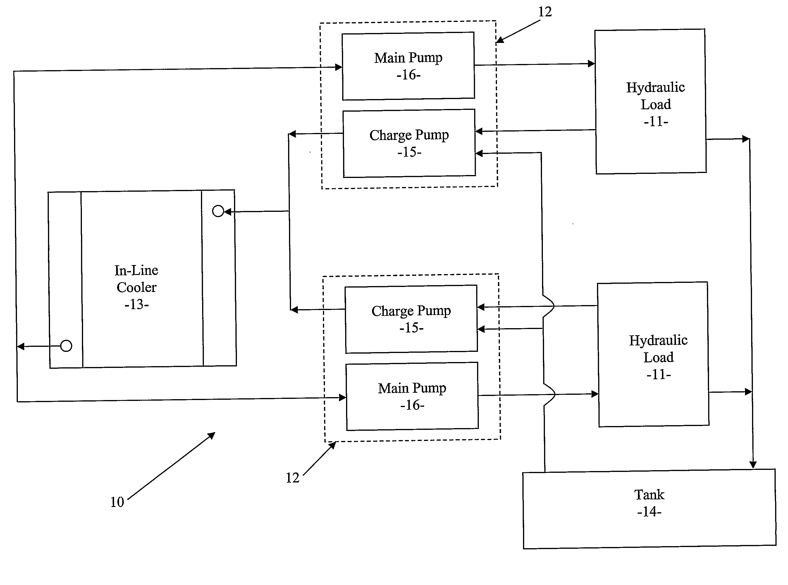
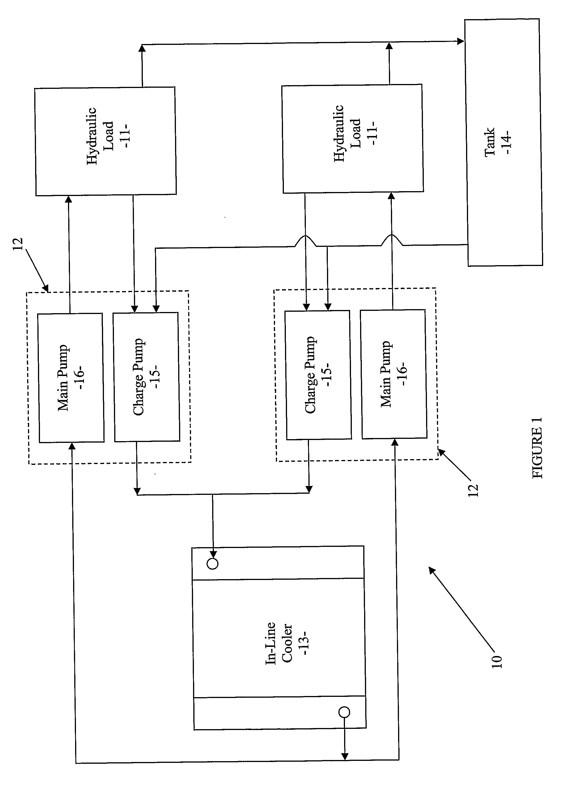
[0034]A hydraulic apparatus in the form of a hydrostatic drive apparatus 10 according to the preferred embodiment of the present invention is depicted in FIG. 1. The hydrostatic drive apparatus 10 drives a plurality of hydraulic motors 11.

[0035]Apparatus 10 comprises a pair of hydraulic fluid pump assemblies 12, a hydraulic fluid cooler 13, and a hydraulic fluid tank or reservoir 14.

[0036]Each pump assembly 12 includes a charge pump 15 and a main pump 16. A first inlet of each charge pump 15 is connected to an outlet of the tank 14 so that each charge pump 15 is able to draw low pressure hydraulic fluid which is held in the tank 14 through the outlet of the tank 14. An outlet of each charge pump 15 is connected to an inlet of the fluid cooler 13 so that each charge pump 15 is able to pump high pressure hydraulic fluid to the inlet of the fluid cooler 13 and through the cooler 13.

[0037]Fluid cooler 13 also includes an outlet which is connected to an inlet of the main pump 16 of each ...


PUM


Abstract

A hydraulic drive apparatus comprises a main pump for pumping hydraulic fluid through a hydraulic load, a charge pump for continuously pumping pressurised hydraulic fluid to the main pump, and a hydraulic fluid cooler. At least a portion to the hydraulic fluid pumped through the hydraulic load is returned under pressure to the charge pump and the charge pump pumps the pressurised hydraulic fluid through the hydraulic fluid cooler to the main pump.

Description

FIELD OF THE INVENTION[0001]The present invention relates generally to hydraulic apparatus and, in particular, to hydraulic apparatus which require cooled hydraulic fluid for circulating through the apparatus.[0002]Although the invention will be described with particular reference to hydrostatic drive apparatus it will be appreciated that this is by way of example only and that the invention may be used in relation to other hydraulic drive apparatus.BRIEF DISCUSSION OF THE PRIOR ART[0003]Various types of plant and equipment such as earthmoving machines include hydraulic apparatus which are in the form of hydrostatic drive apparatus. The ability of these drive apparatus to operate under sustained loads in relatively high ambient temperatures such as 22° C. and above has traditionally been limited by their ability to adequately cool the hydraulic fluid which circulates through them.[0004]In full-flow hydraulic system hydrostatic drive apparatus, power is transmitted from a hydraulic p...

Claims


Application Information

Patent Timeline
IPC IPC(8): F15B21/04F15B21/0423
CPCF15B21/042F15B2211/613F15B2211/20592F15B21/0423F15B21/04
Inventor SMITH, NORMAN JOHN
Owner TITAN RES & INNOVATIONS
Learn More