
Braking control device

a technology of braking control and control device, which is applied in the direction of brake system, vehicle components, brake components, etc., can solve the problems of noise bothering the occupants of vehicles, and achieve the effect of reducing operating noise, reducing operating noise, and reducing fluid pressure control performan

Active Publication Date: 2012-09-04
ADVICS CO LTD
View PDF4 Cites 3 Cited by
  • Summary
  • Abstract
  • Description
  • Claims
  • Application Information

AI Technical Summary

Benefits of technology

The present invention provides a braking control device that reduces the noise generated by the drive frequency of the proportional electromagnetic valve without reducing the performance of fluid pressure control. The device includes required pressure adjustment precision index and required operating noise reduction index settings means for adjusting the drive frequency of the proportional electromagnetic valve based on the priority of fluid pressure adjustment and reducing operating noise. The device also includes a frittical coefficient acquiring means for acquiring the frictional coefficient of the road surface on which the vehicle is positioned to set the required operating noise reduction index. The required operating noise reduction index is set to a value that increases with decreased frictional coefficient of the road surface. The device further includes a control mode determining means for determining the control mode of the braking force and drive frequency setting means for setting the drive frequency of the proportional electromagnetic valve accordingly. This allows for precise control of the braking force while reducing operating noise for the vehicle occupants.

Problems solved by technology

The noise is therefore bothersome to vehicle occupants.

Method used


Image

  • Braking control device
  • Braking control device
  • Braking control device

Examples


Embodiment Construction

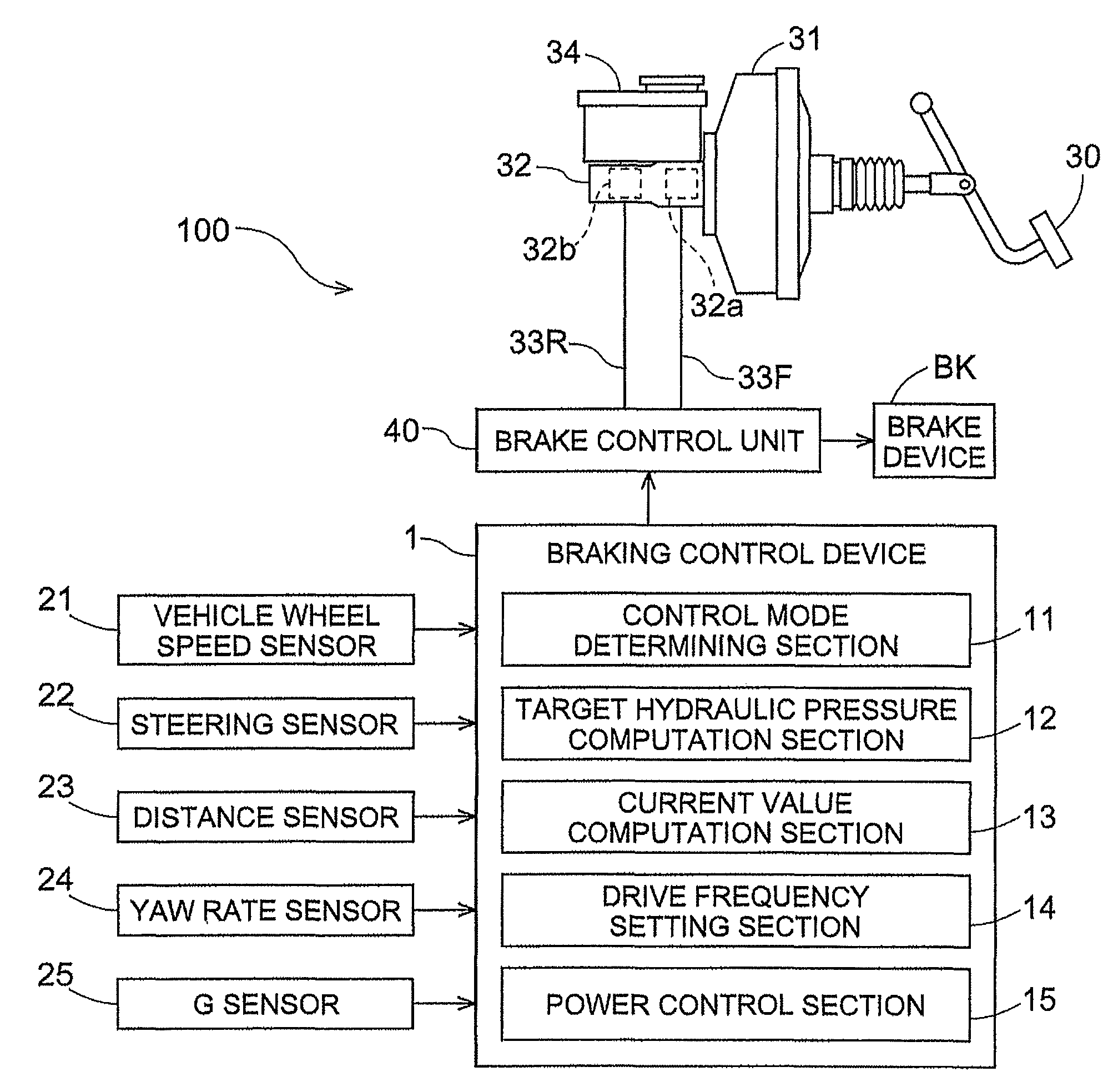
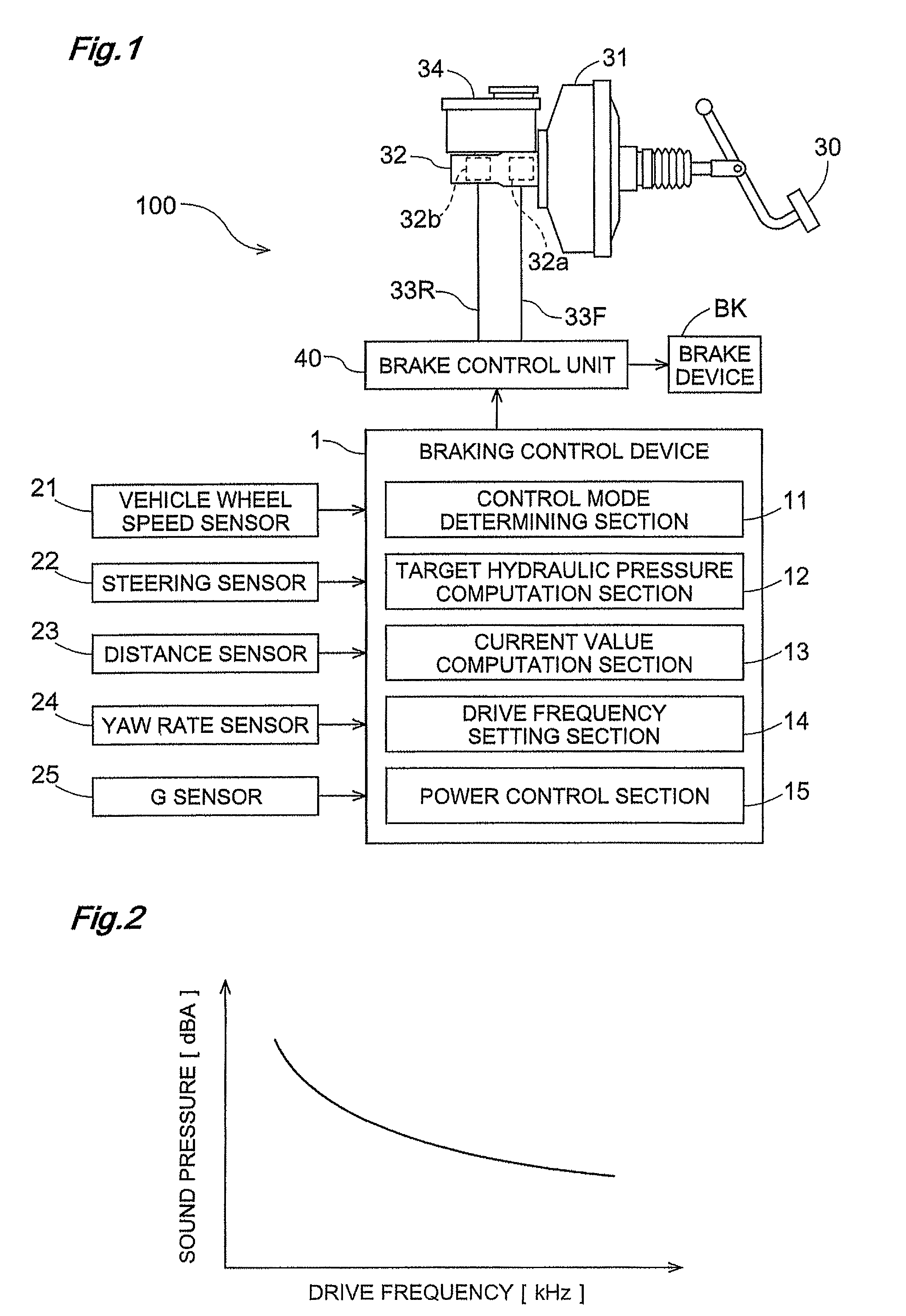
[0032]Embodiments of the present invention will next be described based on the drawings. FIG. 1 is a view schematically showing the control blocks of a brake system 100 to which the braking control device 1 of the present invention is provided. In the present embodiment, the braking control device 1 is provided to a vehicle, and the braking control device 1 adjusts a fluid pressure in accordance with the degree of opening of a proportional electromagnetic valve 49 (see FIG. 5) driven at a set drive frequency, and controls braking force on the basis of the adjusted fluid pressure.

[0033]The brake system 100 has a control system for augmenting the force with which a brake pedal 30 is depressed (depressing force) through the use of a booster 31, transmitting the augmented force to a tandem-type master cylinder 32, and transmitting the pressure of brake fluid in the master cylinder 32 from a brake control unit 40 to a brake device BK.

[0034]The master cylinder 32 has a structure for simul...


PUM


Abstract

A braking control device which adjusts fluid pressure according to the degree of opening of a proportional electromagnetic valve driven at a set drive frequency, and controls a braking force on the basis of the adjusted fluid pressure, comprises a required pressure adjustment precision index setting mechanism for setting a required pressure adjustment precision index on the basis of the precision of pressure adjustment required when the fluid pressure is adjusted according to a required braking force, required operating noise reduction index setting mechanism for setting a required operating noise reduction index on the basis of a requirement to reduce operating noise caused by the drive frequency for driving the proportional electromagnetic valve, and drive frequency setting mechanism for setting the drive frequency of the proportional electromagnetic valve on the basis of the set required pressure adjustment precision index and required operating noise reduction index.

Description

BACKGROUND OF THE INVENTION[0001]1. Field of the Invention[0002]The present invention relates to a braking control device for adjusting a fluid pressure according to the degree of opening of a proportional electromagnetic valve driven at a set drive frequency, and controlling a braking force on the basis of the adjusted fluid pressure.[0003]2. Description of the Related Art[0004]Conventional control devices are known in which an excitation current is applied to a linear solenoid to control the driving of a proportional electromagnetic valve, and the object being controlled is controlled by the proportional electromagnetic valve. In one application of this technique, a proportional electromagnetic valve is provided in a braking control device of a vehicle. In such a braking control device, a predetermined current as a control signal is fed from a control device to the linear solenoid of the proportional electromagnetic valve, whereby the proportional electromagnetic valve actuates an...

Claims


Application Information

Patent Timeline
Patent Type & Authority Patents(United States)
IPC IPC(8): B60T8/38B60T8/172B60T8/36B60T15/36B60W40/068
CPCB60T8/36B60T8/3655B60T8/4872
Inventor KOKUBO, KOICHI
Owner ADVICS CO LTD
Learn More