Safing lock mechanism

a technology of safing locks and locks, which is applied in the direction of mechanical control devices, process and machine control, instruments, etc., can solve the problems of not being 100 percent safe, the design of safing locks failing to provide an indication of the mechanism, and the key may be removed or dislodged, etc., to achieve high shock and vibration

Inactive Publication Date: 2008-07-10
SCOT
View PDF30 Cites 87 Cited by
  • Summary
  • Abstract
  • Description
  • Claims
  • Application Information

AI Technical Summary

Benefits of technology

[0009]It is another object to provide a lock able to control interrupts of energy transfer times with one hundred percent safety.
[0012]It is still yet another object to provide a lock able to control interrupts of energy transfer lines while preventing an engaged key from being removed after the mechanism is locked by that key.
[0014]It is a yet further object to provide a lock able to control interrupts of energy transfer lines that issues an audible feedback when the mechanism is locked and that secures the mechanism against accidental unlocking when a safety release is not desired.
[0015]These and other objects may be attained with a key operated rotary locking mechanism able to control interrupts of energy transfer lines regulated by an safe and arm device, even in an environment subjected to high levels of shock and vibration. Both the lock and key combine to form a hermetically sealed mechanism able to function with, or without, a safety release that prevents the key from being removed from the safe and arm mechanism after the mechanism has been locked by that key following a sequence of axial and rotational movements, and that releases the key internally only in response to externally applied mechanical, electrical or optical influence. A detent of the lock mechanism provides audible feedback when the mechanism is locked and secures mechanism from accidental unlocking when a safety release is not desired.

Problems solved by technology

Therefore, all mentioned designs are not one hundred percent safe for the key can be put in and gets locked, and can not be withdrawn only in a case of the initiated arm signal, but can be removed if the arm signal is not initiated, then there is an opportunity of not properly engaging the key initially or of moving the key during servicing with a result that the key may be removed or dislodged even after the arm signal has been initiated.
After consideration of these and other mechanisms, I discovered that contemporary locks either require a safety release that when engaged prevents the key from being removed after the mechanism is locked or otherwise fails to secure the mechanism from accidental unlocking when a safety release is not desired.
Moreover, many contemporary designs of safing locks fail to provide an indication that the mechanism is in a locked mode.

Method used


Image

  • Safing lock mechanism
  • Safing lock mechanism
  • Safing lock mechanism

Examples


Embodiment Construction

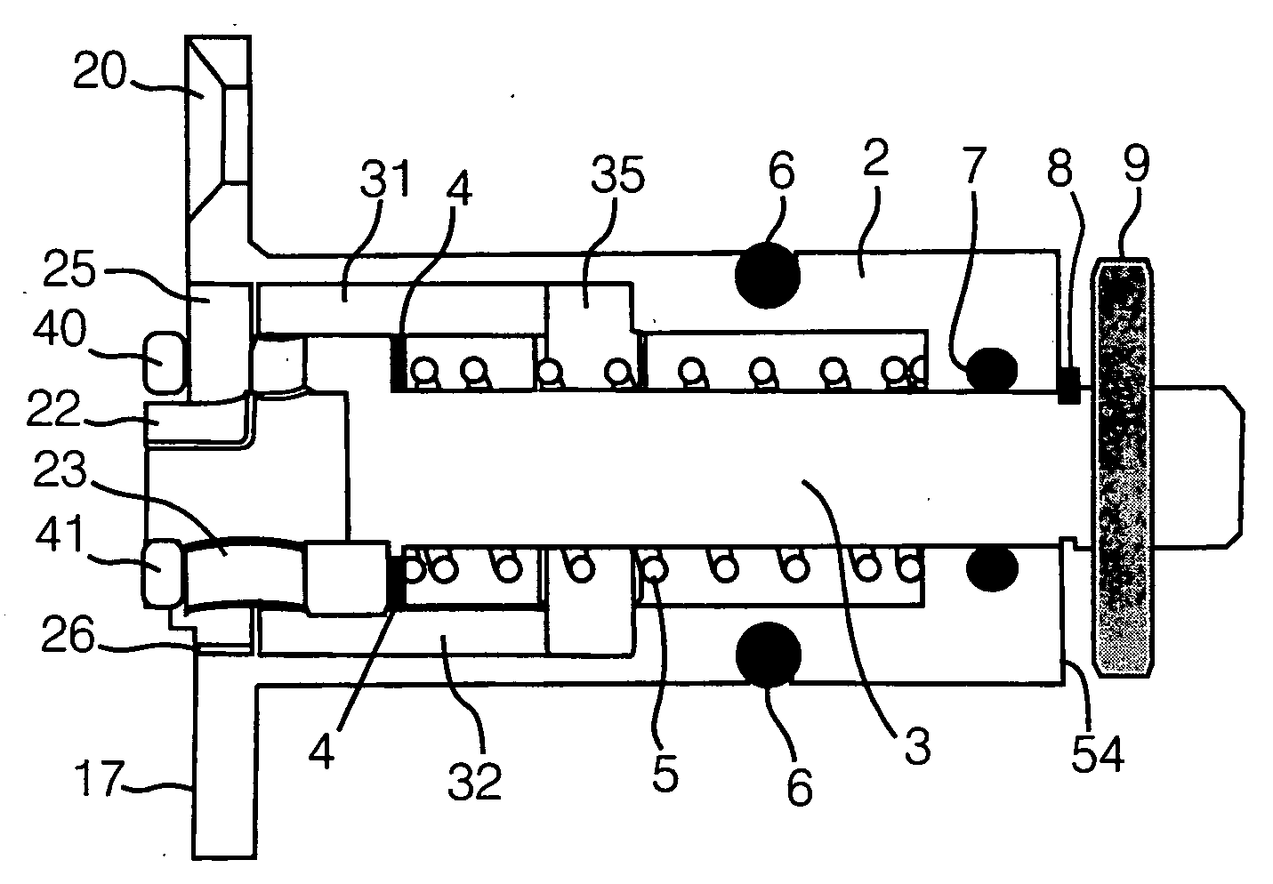
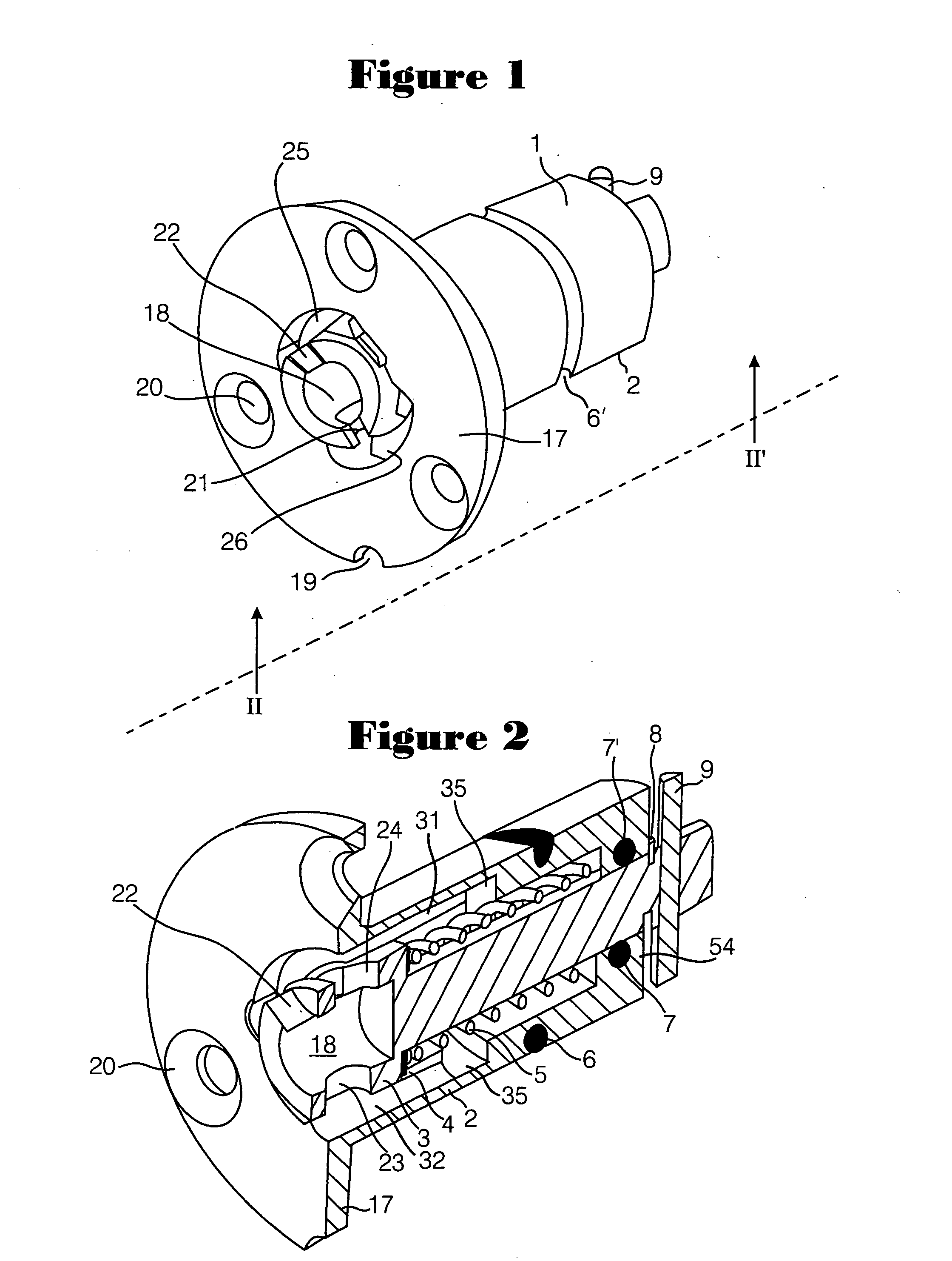
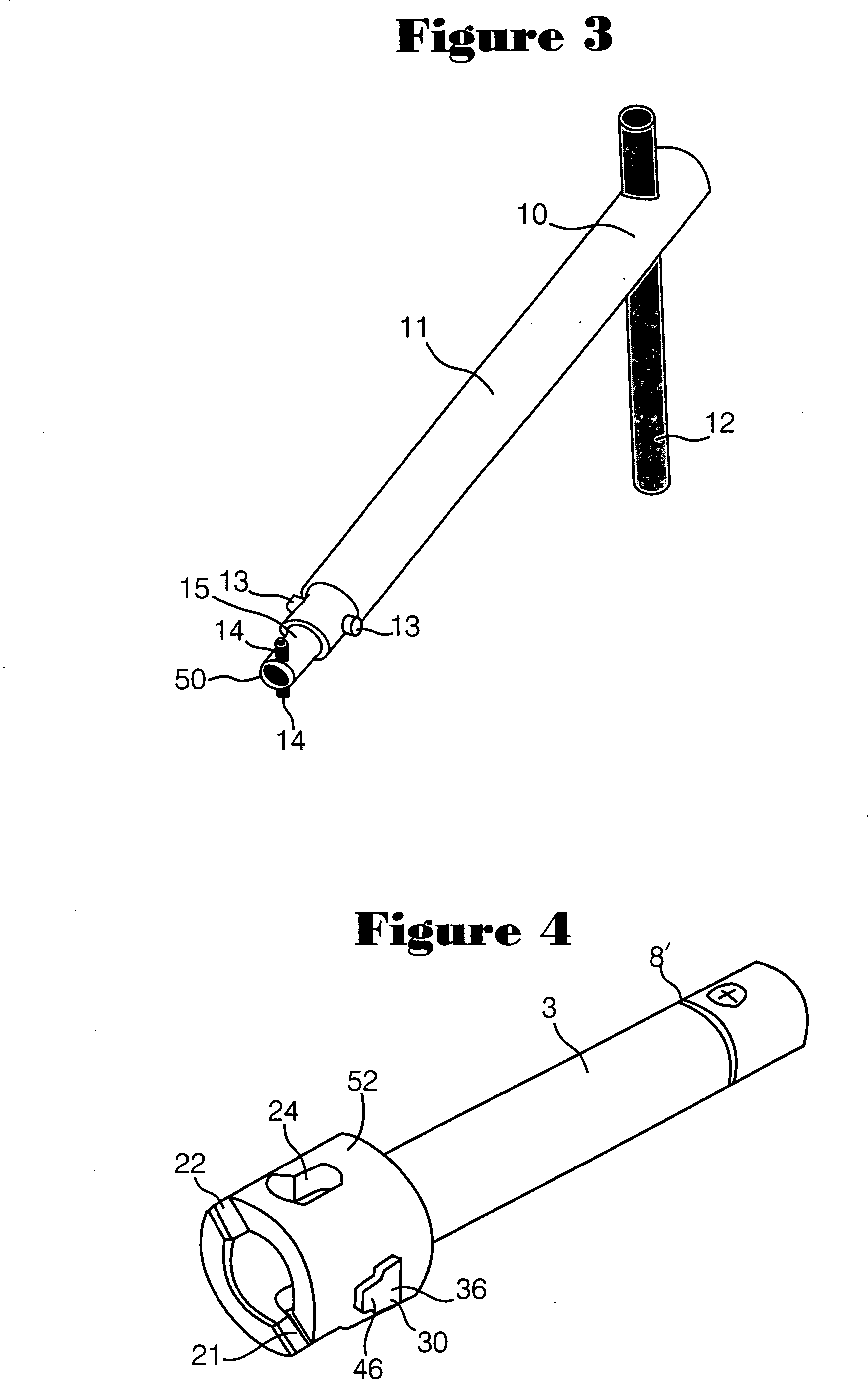
[0038]Turning now to the drawings, FIGS. 1, 2 and 3 collectively illustrate a locking mechanism 1 for a pyrotechnic safing interrupter, that may be constructed with an external lock casing 2, longitudinally extending bolt 3, washer 4, spring 5, retaining ring 8 and interlocking element 9 that may be configured in various shapes and features corresponding with a safety release component. Element 9, although shown as a member radially extending transversely across the distal end of bolt 3, is an exemplar representative of different structural shapes that are oriented by casing 2 to engage and to be operationally restrained by an arming device of lock a safe and arm mechanism in a safe position prior to an intended mission to ensure that output devices secured by lock 1 will not be initiated; consequently, when element 9 is restrained by the arming device, key 10 can not be rotated and may not therefore, be removed from bolt 3 until the arming device is activated to release element 9. ...


PUM


Abstract

A locking mechanism for a pyrotechnic safe and arm interrupter 98 may be constructed with an external lock casing 2, longitudinally extending bolt 3, washer 4, spring 5, retaining ring 8 and interlocking element 9 that may be configured in various shapes and features corresponding with a safety release component. A key 10 may be constructed with key stem 11, handle 12 and two pairs of teeth 13, 14 of different diameters radially protruding from successively reduced diameters along a distal portion of key stem 11. Lock 1 may be installed with notch 19 in alignment with a corresponding feature of the safe and arm interrupter mechanism and fastened in place with mounting holes 20 so that only mounting flange 17 and the key access 18 are external to the interrupter device, panel or door.

Description

BACKGROUND OF THE INVENTION[0001]1. Technical Field[0002]The present invention relates to interrupts of energy transfer lines, and more particularly, to hermetically sealed safing mechanisms for high levels of shock and vibration suitable for working with, or without, a safety release in key operated rotary locks.[0003]2. Related Art[0004]Detonator assemblies typically can only be initiated after a safing mechanism has been unlocked and an interlocking element of the safing mechanism is free to proceed into alignment with a diametrical bore of the detonator. The volatile nature of explosive charges used in aircraft, missiles, space vehicles and pyrotechnic systems for example, require safety features to prevent their inadvertent and hazardous initiation during maintenance of the systems; U.S. Pat. No. 3,728,936 for Arming And Safing Device issued on the 24 Apr. 1973 to Norris and U.S. Pat. No. 4,202,271 for Safe And Arm Device issued on the 13 May 1980 to Day disclose different desi...

Claims


Application Information

Patent Timeline
Patent Type & Authority Applications(United States)
IPC IPC(8): E05B67/36
CPCF42C15/21Y10T70/443Y10T70/5642Y10T70/7492
Inventor SHATSKIN, LEONID
Owner SCOT
Why Eureka
Try Eureka