System and method for turbulent flow drag reduction

a technology of turbulent flow and reduction method, applied in pipeline systems, circuit elements, thin material processing, etc., can solve the problems of reducing speed and fuel efficiency, high cost of pumping, slowing down fluid flow, etc., and achieve the effect of reducing turbulent flow drag

Inactive Publication Date: 2008-07-10
VIRGINIA TECH INTPROP INC
View PDF4 Cites 9 Cited by
  • Summary
  • Abstract
  • Description
  • Claims
  • Application Information

AI Technical Summary

Benefits of technology

[0008]According to one embodiment, the counter-rotating elements comprise counter-rotating strips (e.g., disposed around the circumference of a pipe). In another embodiment, the counter-rotating elements may comprise counter-rotating disks (e.g., disposed along a planar surface). In yet a further embodiment, the counter-rotating elements may comprise a

Problems solved by technology

For example, drag due to aerodynamic forces occurs on many external surfaces such as: aircraft wings, ship hulls, and automobiles and trucks, thereby reducing speed and fuel efficiency.
In addition, turbulent flow drag in pipes slows down the flow of fluids such as water, oil, etc., which can be very expensive to pump.
In the petroleum industry, for example, t

Method used


Image

  • System and method for turbulent flow drag reduction
  • System and method for turbulent flow drag reduction
  • System and method for turbulent flow drag reduction

Examples


Embodiment Construction

[0012]The present invention will now be described with respect to one or more particular embodiments of the invention. The following detailed description is provided to give the reader a better understanding of certain details of embodiments of the invention depicted in the figures, and is not intended as a limitation on the full scope of the invention, as broadly disclosed and / or claimed herein. In addition, for purposes of this disclosure, it should be understood that, unless otherwise indicated, “a” means one or more.

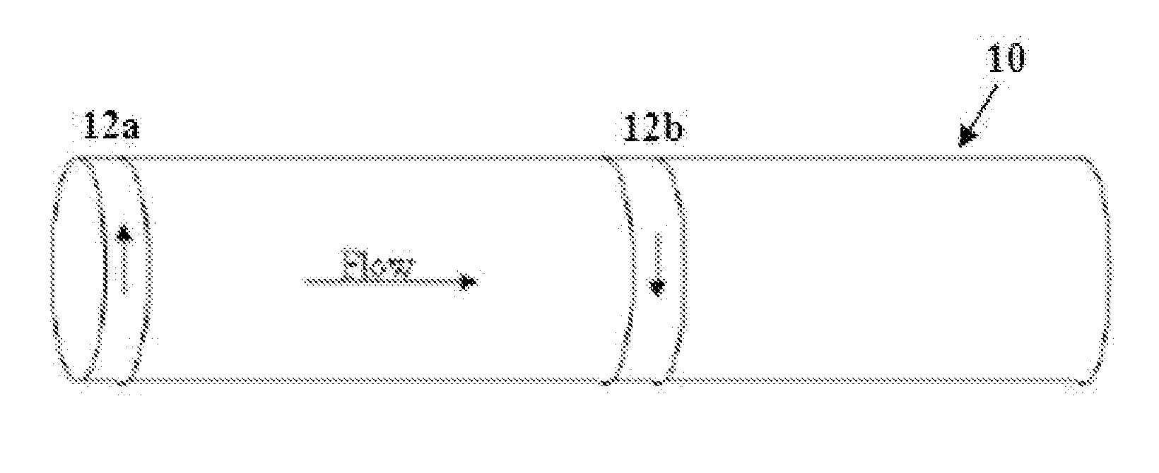
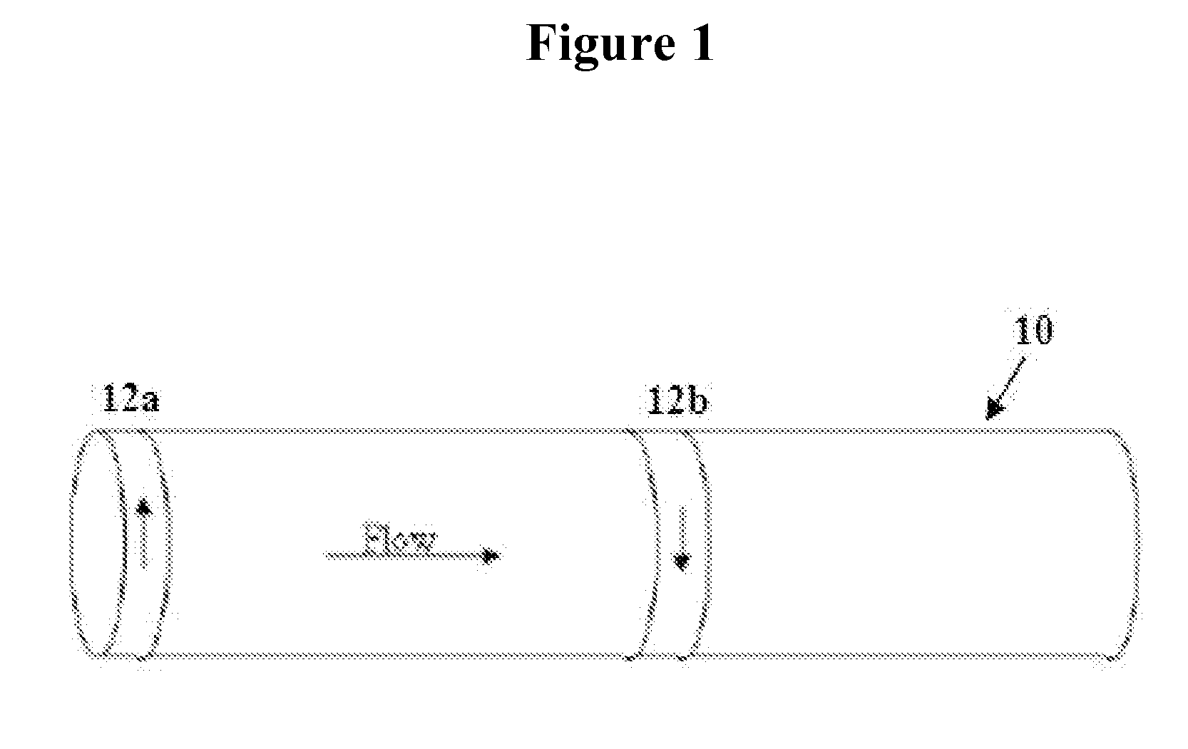
[0013]FIG. 1 shows an illustration of discrete counter-rotating elements (12a), (12b), for example counter-rotating strips, disposed adjacent to a bounding surface (10), such as a section of pipe. The counter-rotating elements (12a), (12b) are rotated in opposite directions as shown. As the elements (12a), (12b) are rotated in their respective directions, each generates a small counter-rotating flow effective to disrupt or reduce stream-wise vortices and / or traveling...


PUM


Abstract

The invention provides a system and method for turbulent flow drag reduction using discrete counter-rotating elements disposed adjacent a bounding surface and arranged to effectively disrupt or suppress stream-wise vortices and/or traveling waves thereby reducing turbulence and increasing fluid flow. In embodiments, the counter-rotating elements effectively decouple the interaction between traveling waves and stream-wise vortices. By using discrete counter-rotating elements as disclosed, the energy input to the counter-rotating elements is advantageously less than the energy gained from the flow rate increase. The counter-rotating elements may comprise e.g., counter-rotating strips, counter-rotating disks or a plurality of sequentially activated jets. In addition, the bounding surface may comprise a section or pipe, a substantially planar surface, etc. The counter-rotating elements may be used along a section of a pipe, on a surface of an aircraft wing, in HVAC systems, etc. Examples of fluids include, but are not limited to: water, air, natural gas, oil, etc.

Description

CROSS-REFERENCE TO RELATED APPLICATIONS[0001]This application relies on the disclosure of and claims the benefit of the filing date of U.S. provisional patent application No. 60 / 802,161, filed 22 May 2006, the entire disclosure of which is hereby incorporated herein in its entirety.BACKGROUND OF THE INVENTION[0002]The present invention relates to a system and method of turbulent flow drag reduction.Description of Related Art[0003]Turbulent fluid flows are primarily characterized by chaotic, stochastic property changes and may be readily distinguished from laminar flows based on the dimensionless Reynolds number, Re (where flows with a Re above 2300 are considered turbulent). As fluid flows through e.g., a pipe at very low speeds, the flow remains laminar. However, as the speed increases, at some point a transition is made at the boundary layer from a steady laminar flow to a “chaotic” turbulent flow. Although the causal factors for the laminar-turbulent transition are complex, it is...

Claims


Application Information

Patent Timeline
IPC IPC(8): F15D1/02F15C3/00
CPCF17D1/16F15D1/06Y10T137/206
Inventor DUGGLEBY, ANDREW T.BALL, KENNETH
Owner VIRGINIA TECH INTPROP INC
Why Eureka
Try Eureka