Radiant heat wall covering system

Active Publication Date: 2008-07-10
KELLER JAMES P MR
View PDF46 Cites 14 Cited by
  • Summary
  • Abstract
  • Description
  • Claims
  • Application Information

AI Technical Summary

Benefits of technology

[0005]The present invention provides, in a second aspect, a wall covering system which includes a first wall covering portion having a top side with decorative finish directly applied thereto, and a second wall covering portion. The first portion is releas

Problems solved by technology

In a typical radiant heating system, the conduits are attached via brackets to the hidden side of wall cover

Method used


Image

  • Radiant heat wall covering system
  • Radiant heat wall covering system
  • Radiant heat wall covering system

Examples


Embodiment Construction

[0016]In accordance with the principals of the present invention, a radiant wall covering system and methods for radiant wall heating are provided.

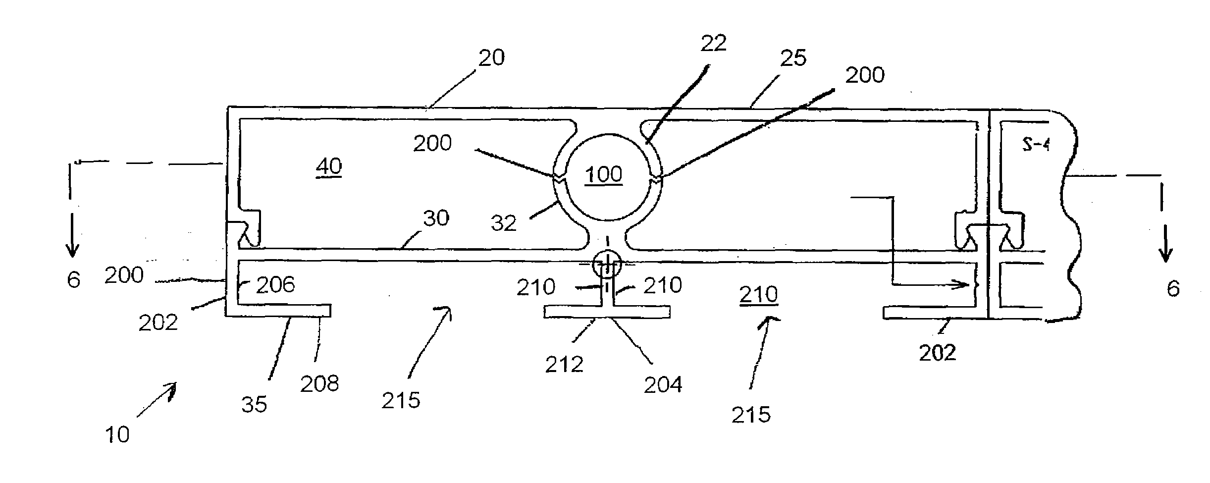
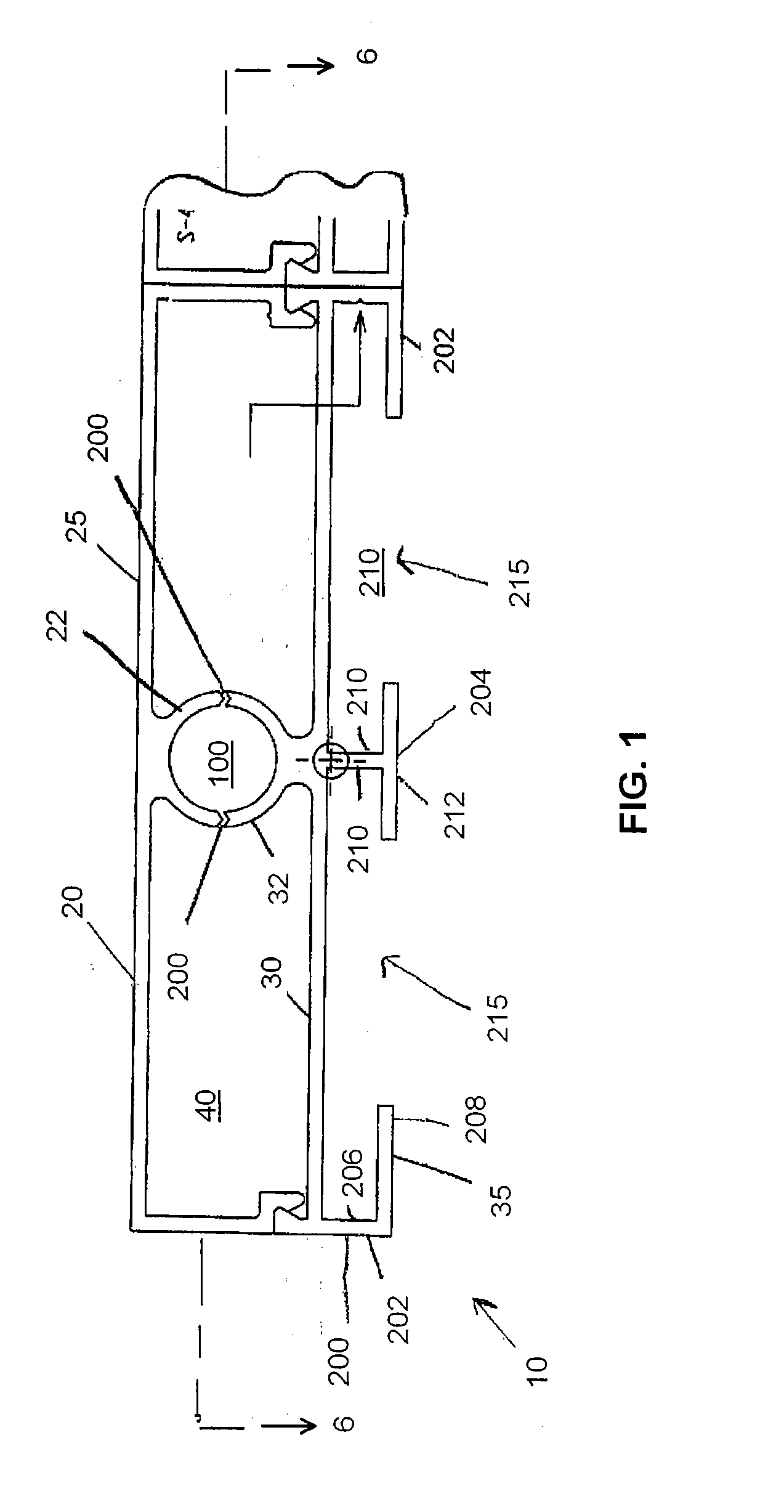
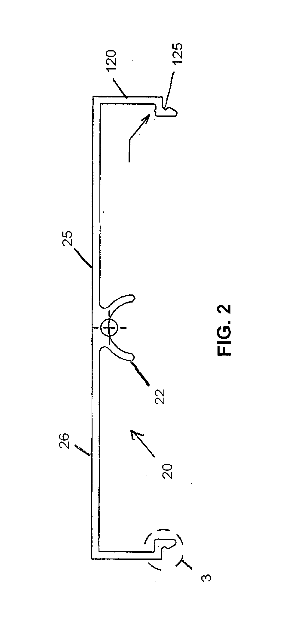
[0017]In an exemplary embodiment depicted in FIG. 1, a wall covering system 10 includes a first or outer wall covering portion 20 and a second or interior wall covering portion 30 for supporting the first portion. A top surface 25 of first portion 20 is utilized in a manner similar to a top surface of typical wall covering, e.g., located adjacent habitable space and having an aesthetically pleasing surface such as paint, texture, or wall paper thereon. A bottom surface 35 of second portion 30 is utilized in a manner similar to a typical support material, e.g., connected to wall studs such as wall studs 300 (FIGS. 6-7), concrete walls or other such wall covering support to support a wall covering placed thereon and / or attached thereto. Multiple instances of system 10 may be located adjacent one another to form a wall covering on such wall ...


PUM


Abstract

A wall covering system for radiant heating includes a first wall covering portion and a second wall covering portion. The first portion is releasably connectable to the second portion in a direction substantially perpendicular to an outer surface of the first portion. The first portion includes a bottom side and top channel portion downwardly depending from the bottom side. The second portion includes a top side and a bottom channel portion extending upwardly from the top side. The top channel portion and the bottom channel portion bound a channel for receiving a heating conduit. The channel extends longitudinally relative to the first portion and the second portion.

Description

FIELD OF THE INVENTION [0001]The present invention relates to wall covering systems and in particular systems and methods for radiant heat wall covering systems.BACKGROUND OF THE INVENTION [0002]Radiant heating systems for wall coverings heat the walls of a dwelling, office, or other building, which then heat the habitable space thereof. Tile, hardwood floors or other aesthetically desirable materials are typically used for wall covering in combination with radiant heating systems. The radiant heating conduits are usually located on an opposite side of the wall covering relative to a surface visible from a room interior. The conduits are thus usually installed and maintained in an area (e.g., behind a wall) which is not directly accessible to the inhabited space portion of a room. Often, insulation is desirable to inhibit heat from the heated space from transferring toward an unheated space or the ambient environment. Insulation and a wall itself are thus usually placed over such he...

Claims


Application Information

Patent Timeline
IPC IPC(8): F24D19/02
CPCF24D3/142F24D3/127Y02B30/00
Inventor KELLER, JAMES
Owner KELLER JAMES P MR
Why Eureka
Try Eureka