Process for two-step fracturing of oil shale formations for production of shale oil

a technology of oil shale formation and two-step fracturing, which is applied in the direction of fluid removal, earth drilling and mining, borehole/well accessories, etc., can solve the problems of contaminating aquifers, requiring days or even weeks to clean up, and limited fracturing produced by high-pressure gas pulses

Inactive Publication Date: 2008-07-10
YOUNG MICHAEL ROY
View PDF14 Cites 45 Cited by
  • Summary
  • Abstract
  • Description
  • Claims
  • Application Information

AI Technical Summary

Problems solved by technology

Third, the heated portion of the formation must be permanently isolated from any adjacent aquifers.
Extensive caving also occurs in the well bore leaving debris that may require days or even weeks to clean up.
Even so, the fracturing produced by application of high-pressure gas pulses is limited.
Heating fluids injected into the formation, while necessary and effective for extracting shale oil deposits, may contaminate aquifers.

Method used


Image

  • Process for two-step fracturing of oil shale formations for production of shale oil
  • Process for two-step fracturing of oil shale formations for production of shale oil
  • Process for two-step fracturing of oil shale formations for production of shale oil

Examples


Embodiment Construction

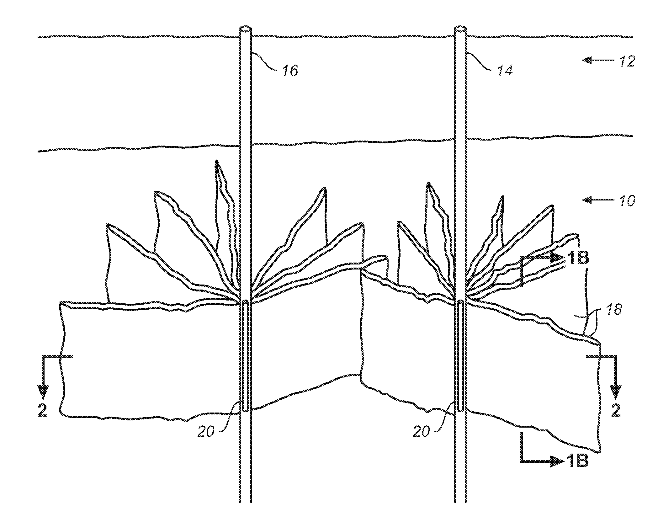
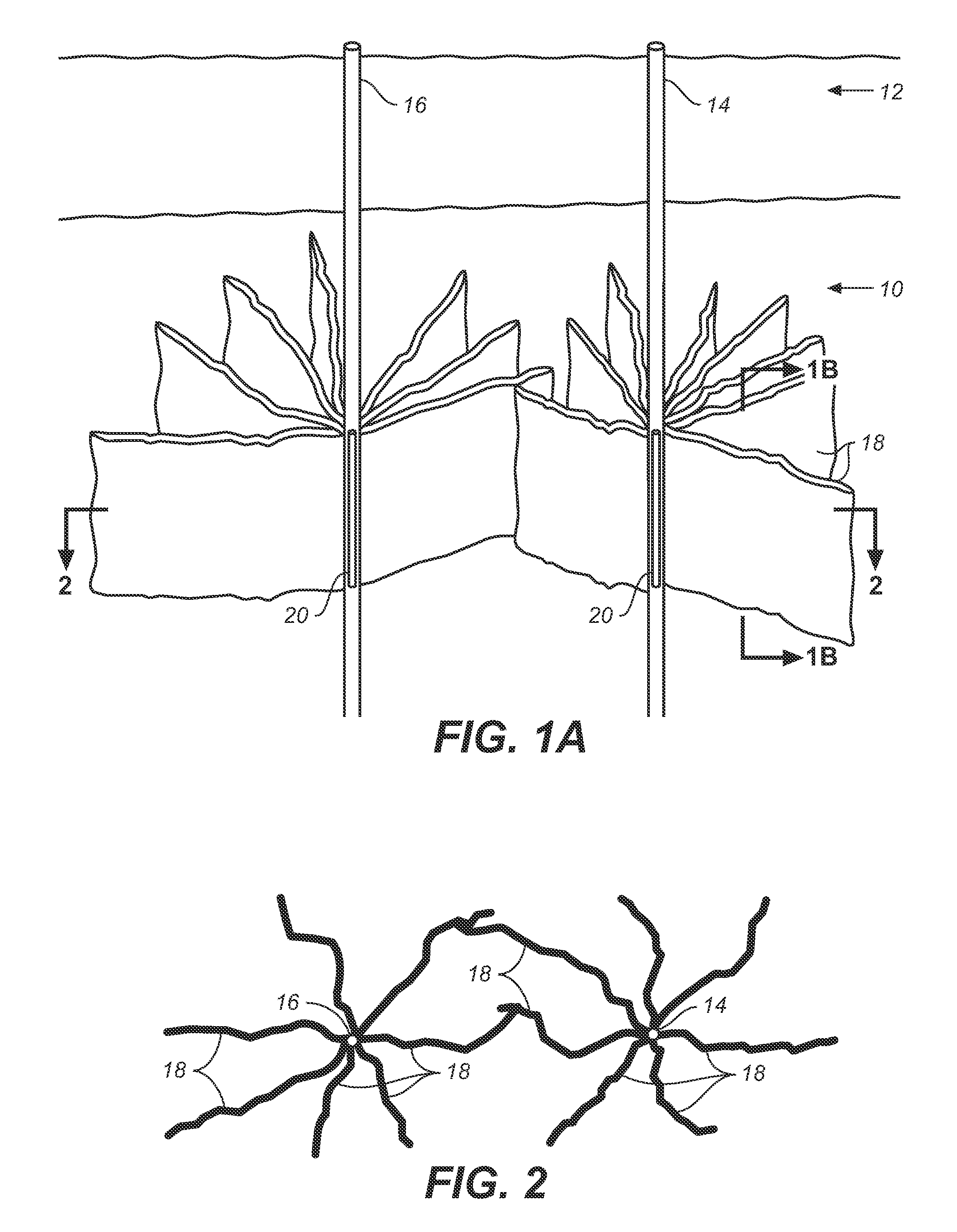
[0010]FIG. 1A is a perspective view of the target zone of a subsurface formation in which two wells have been drilled and an initial set of fractures has been created.

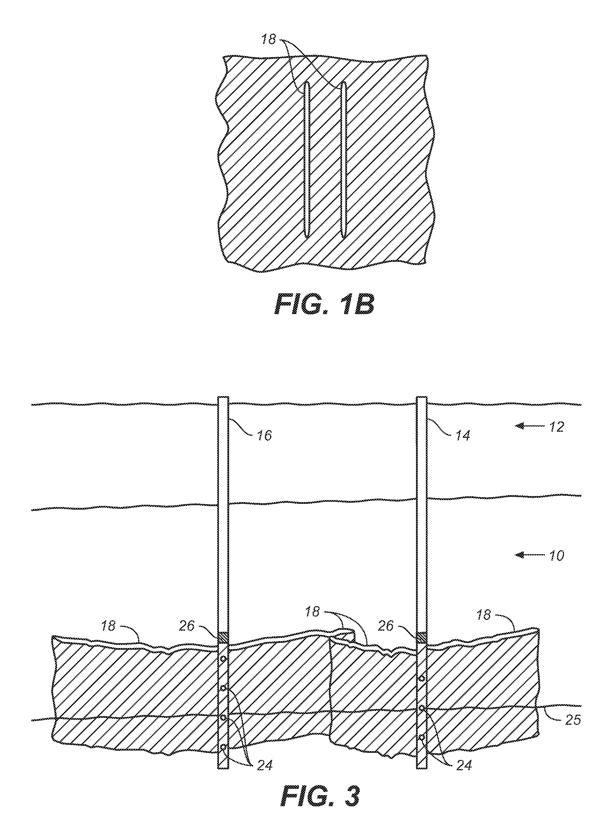
[0011]FIG. 1B is a sectional elevational of a portion of the formation shown in FIG. 1A taken along line 1A showing representative fractures in the formation.

[0012]FIG. 2 is a sectional plan view of a horizontal section of the target zone depicted in FIG. 1.

[0013]FIG. 3 is a perspective view similar to that of FIG. 1A wherein a mixture of modified ANFO has been injected into the well bores and several C-4 charges positioned according to the invention.

[0014]FIG. 4A is a perspective view similar to that of FIG. 3 showing a secondary set of fractures created by detonation of the modified ANFO mix according to the invention.

[0015]FIG. 4B is a detail sectional elevational view of a portion of FIG. 4A showing the initial and secondary set of fractures in the formation and sand particles in the fractures.

[0016]FIG. 5 is a pla...


PUM


Abstract

A process for in situ production of shale oil comprises fracturing the target zone 10 of an shale oil formation using a two step approach. First, an initial set of fractures 18 is developed in the formation by using high pressure gas pulses. Second, a secondary set of fractures 28 extending and further fracturing the initial set of fractures 18 is created using a modified ANFO mix 22 wherein rubber particles acting as solid fuel are blended in with ammonium nitrate and fuel oil. The solid fuel enhances the fracturing characteristics of ANFO while minimizing its crushing and compacting tendencies. Hot high pour point oil is then injected into the formation and forced into the receptor well 16 where it is pumped to the surface. By circulating oil in the formation at carefully controlled temperatures, kerogen can be decomposed at the optimum rate to maximize the amount of oil recovered and yield high quality shale oil. High pour point oil reaching cooler extremities of the fractured formation will solidify creating an impermeable perimeter barrier 34 around the target zone 10.

Description

CROSS-REFERENCE TO RELATED APPLICATION[0001]This application claims the benefit of U.S. Provisional Application No. 60 / 878,356, filed Jan. 4, 2007.BACKGROUND OF THE INVENTION[0002]1. Field of the Invention[0003]The invention is directed to a process for fracturing a tight subsurface formation, and more particularly to a two-step process for fracturing an oil shale formation for production of shale oil. One aspect of the invention is directed to a process for circulation of high pour point oil into the fractured formation for decomposition of in situ kerogen into and recovery of shale oil.[0004]2. Description of the Prior Art[0005]Production of shale oil involves at least three major technological requirements. First, a process is needed that results in the flow of fluids through a subsurface formation. Second, heating of the formation to decompose kerogen must be carefully controlled. Third, the heated portion of the formation must be permanently isolated from any adjacent aquifers....

Claims


Application Information

Patent Timeline
Patent Type & Authority Applications(United States)
IPC IPC(8): E21B43/263
CPCE21B43/263E21B43/2405
Inventor YOUNG, MICHAEL ROY
Owner YOUNG MICHAEL ROY
Why Eureka
Try Eureka