Contactless Magnetic Potentiometer

Inactive Publication Date: 2008-07-10
SPECTRA SYMBOL
View PDF5 Cites 13 Cited by
  • Summary
  • Abstract
  • Description
  • Claims
  • Application Information

AI Technical Summary

Benefits of technology

[0007]A potentiometer is described wherein the conductive and resistive traces of the potentiometer are contained within a sealed channel formed of non-conductive material. The gap between the conductive and resistive traces is bridged by a tap formed from a conductive permanent magnet or by a conductive ferromagnetic material. A magnetic force may be applied to the tap through the surface of the sealed channel by means of a magnet loc

Problems solved by technology

Over time, the actuating pressure on the tapping pressure pin strips the upper plastic film on the resistive path, causing the film to wear out.
This decreases the life of the film potentiometers and

Method used


Image

  • Contactless Magnetic Potentiometer
  • Contactless Magnetic Potentiometer
  • Contactless Magnetic Potentiometer

Examples


Embodiment Construction

[0021]Referring now to the figures, a description of some embodiments of the present invention will be given. It is expected that the present invention may take many other forms and shapes, hence the following disclosure is intended to be illustrative and not limiting, and the scope of the invention should be determined by reference to the appended claims.

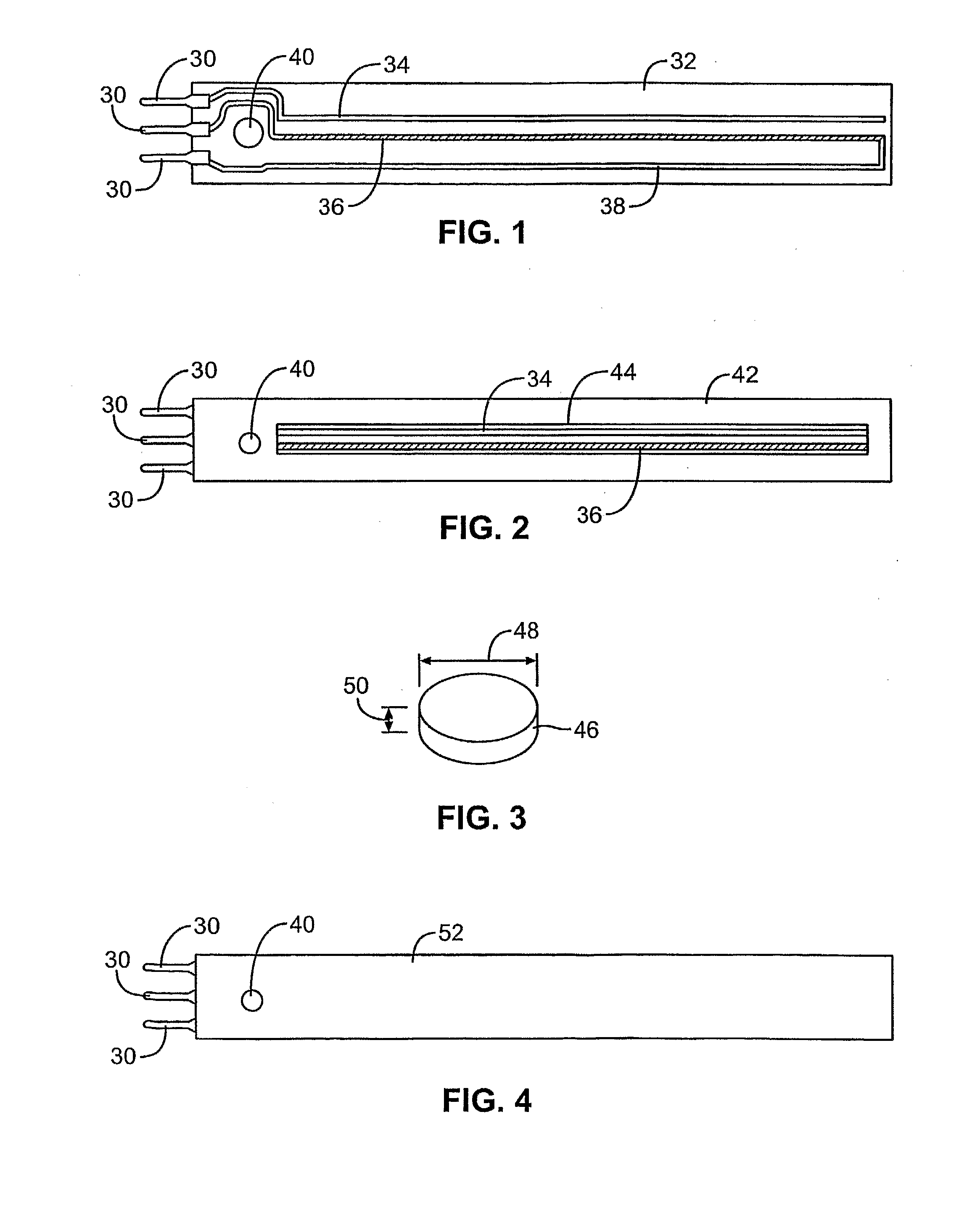
[0022]In some embodiments, the invention comprises a sealed channel containing conductive and resistive traces; a tap comprised of one or more materials that are measurably subject to magnetic forces; and an external control element that is measurably subject to magnetic forces. In some embodiments, a permanent magnet or an electromagnet is used as either the tap or the external control element. In some embodiments, because the channel is sealed, there is no physical contact between the tap and the external control element during operation of the invention.

[0023]FIGS. 1 through 4 illustrate the components of one embodiment of the i...


PUM

PropertyMeasurementUnit
Lengthaaaaaaaaaa
Magnetic fieldaaaaaaaaaa
Electrical resistanceaaaaaaaaaa

Abstract

A contactless potentiometer is described wherein the conductive and resistive traces of the potentiometer are contained within a sealed channel formed of non-conductive material. The electrical gap between the conductive and resistive traces is bridged by a magnetically reactive contactless tap. A magnetic force is applied to the tap through the surface of the channel holding the conductive and resistive traces. This provides a drawing magnetic force to the tap which pulls the tap against the traces and allows for changing the resistance of the potentiometer by laterally moving the tap along the traces as the tap moves to follow the motion of the external force.

Description

CROSS-REFERENCE TO RELATED APPLICATIONS[0001]This application claims priority to patent application number 20 2005 010 424.8 filed in the German Patent and Trademark Office on Jun. 29, 2005.BACKGROUND OF THE INVENTION[0002]1. Field of the Invention[0003]The present invention relates to a tap for potentiometers, and more particularly to a contactless tap for resistive surfaces by means of magnets.[0004]2. Background and Related Art[0005]Film potentiometers on the market operate with an actuating pressure on the tapping pressure pin. Over time, the actuating pressure on the tapping pressure pin strips the upper plastic film on the resistive path, causing the film to wear out. As the plastic film on the resistive path wears out, the resistive path may become increasingly pre-formed and as a result the top layer can pre-actuate electrically, or the contact wiper can physically tear the top layer. This decreases the life of the film potentiometers and can result in locations of lost cont...

Claims


Application Information

Patent Timeline
IPC IPC(8): H01C10/30H01C17/00
CPCY10T29/49082H01C10/366
Inventor MALZAHN, HEINZ HERBERT
Owner SPECTRA SYMBOL
Why Eureka
Try Eureka