
Mounting device for an aircraft engine comprising two thrust recovery rods with a double rear mechanical connection

a technology for aircraft engines and mounting devices, which is applied to machines/engines, machine supports, other domestic objects, etc., can solve the problems of generating mass and space requirements that are difficult to meet, and achieve the effect of facilitating the design of thrust load recovery devices and facilitating the mounting of these connections

Active Publication Date: 2008-07-17
AIRBUS OPERATIONS (SAS)
View PDF3 Cites 20 Cited by
  • Summary
  • Abstract
  • Description
  • Claims
  • Application Information

AI Technical Summary

Benefits of technology

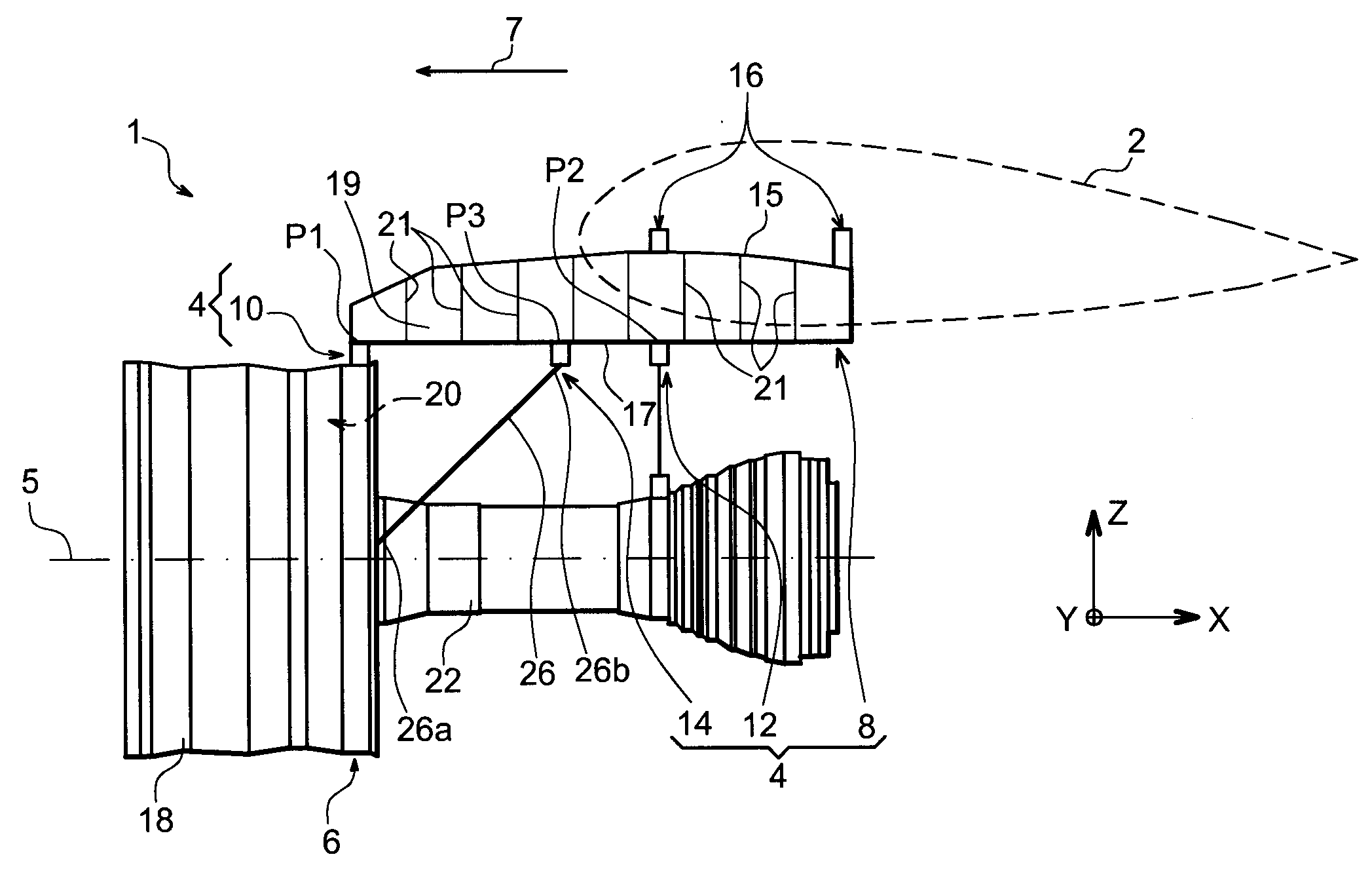
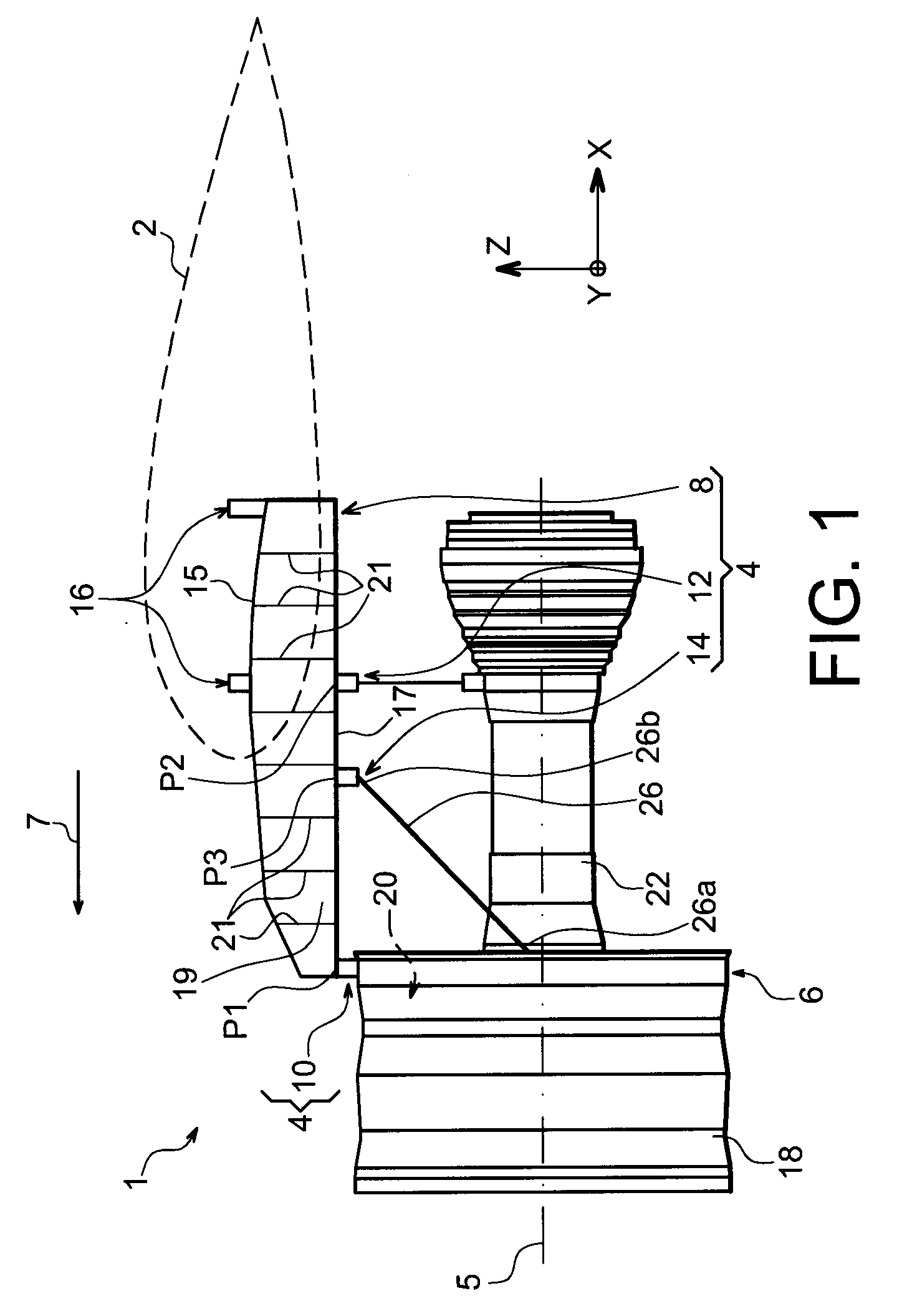
[0015]Thus, it should be understood that the present invention proposes a particular design allowing a “Fail Safe” function to be provided without having to double up on some parts such as the crossbar or the connection axis associated therewith, which secures to advantage a gain in terms of mass and space requirement.
[0018]In this way, it follows also from what has been said before that the proposed arrangement ensures a particular dissociation between the load path in normal operation and the so-called “Fail Safe” load path as encountered in a failure / breakage mode, which facilitates the design of the thrust load recovery device.
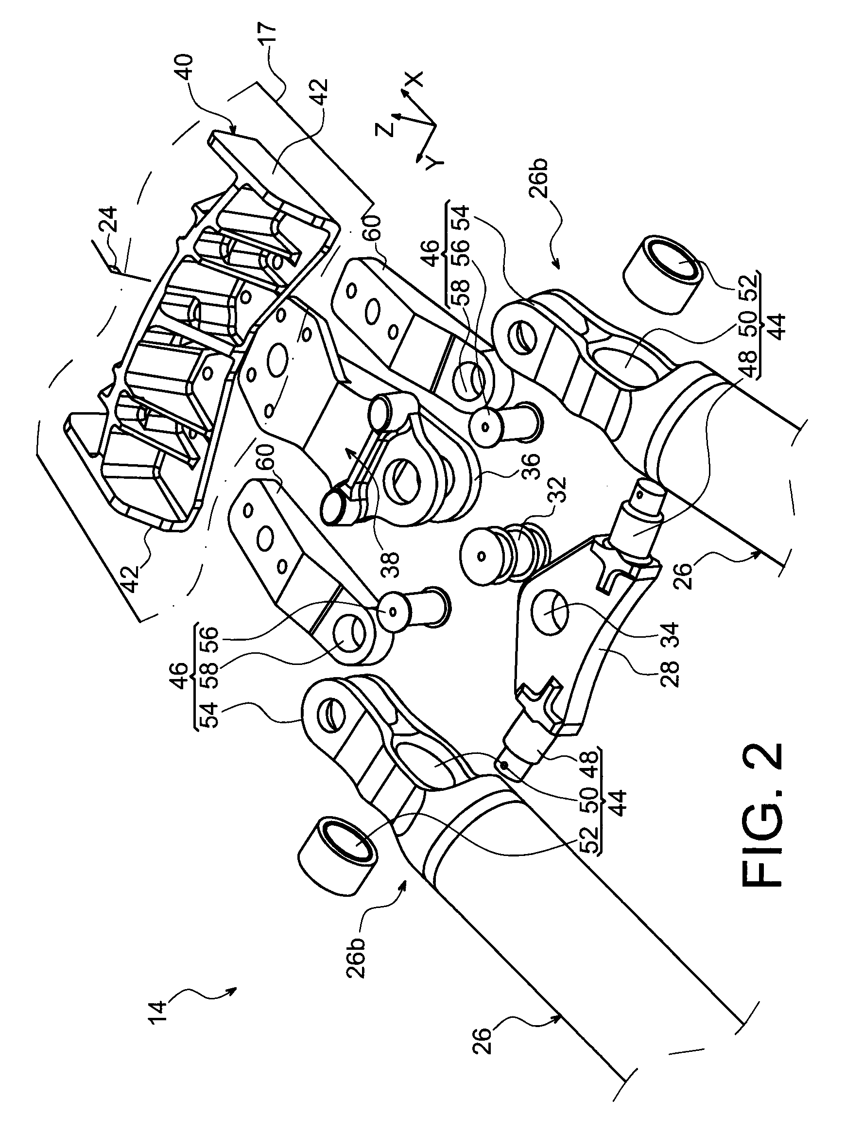
[0019]Moreover, as mentioned above, provision is made for the first mechanical connection to be implemented using a pin provided on the crossbar, passing through an orifice provided in the rear end of the rod, which overall facilitates the mounting of this connection.
[0021]Preferably, the orifice provided in the rear end of the rod is equipped with a ball-and-socket joint passed through by the pin provided on the crossbar. Additionally, it is preferentially arranged such that each of the two pins provided on the crossbar is arranged so as to extend substantially transversely relative to the mounting device, which facilitates the mounting of this connection. In this configuration where each pin extends therefore substantially along the transverse direction of the device or in a way slightly inclined relative thereto, the installation and manipulation of the equipment for mounting the rear rod ends generates almost no risk of deterioration of the engine unit, insofar as the free tip of each pin is orientated towards an uncrowded area of this engine unit. Moreover, the ease of assembly obtained by an arrangement of this kind allows a saving to be made in terms of assembly time, the latter being moreover also optimised by the fact that the rear ends of the lateral rods can now easily be fitted into their associated pin by a straightforward substantially lateral movement of these rods, initially connected to the engine by their front end.

Problems solved by technology

If this solution is relatively widespread in prior art embodiments, it is still nonetheless disadvantageous in terms of mass and space requirement generated, mainly because of the doubling up on a certain number of parts, such as the crossbar or connection axis associated therewith.
Moreover, this solution does not allow the load path in normal operation and the so-called “Fail Safe” load path encountered in a failure / breakage mode to be fully dissociated, which poses obvious problems of design.

Method used


Image

  • Mounting device for an aircraft engine comprising two thrust recovery rods with a double rear mechanical connection
  • Mounting device for an aircraft engine comprising two thrust recovery rods with a double rear mechanical connection
  • Mounting device for an aircraft engine comprising two thrust recovery rods with a double rear mechanical connection

Examples


first embodiment

[0066]With reference now to FIG. 5, showing a rear part of the recovery device 14 according to a second preferred embodiment of the present invention, it can be seen that the main difference with the first embodiment described above lies in the design of the connection fitting 38 carrying the crossbar 28. As such, it should be noted that this figure taken in cross-section along the vertical and longitudinal median plane 24 of the mounting device, the elements bearing the same numerical references as in the other figures correspond to identical or similar elements.

[0067]The connection fitting 38 has an upper surface added in a fixed way under the lower spar 17 with which it is preferably in contact, the assembly means used (not shown), for example of the bolt type, coming to engage with a reinforcement fitting 40 housed inside the box, and being preferably in contact with the inner surface of the lower spar 17.

[0068]Nonetheless, unlike the first embodiment, it has an orifice to accom...

second embodiment

[0070]In FIG. 6 showing an alternative for implementing the second embodiment, it can be seen that only the connection of the support fittings 60 differs relative to that of the arrangement shown in FIG. 5, the connection of the crossbar 28 being in fact identical or similar to the one relating to the arrangement shown in this same FIG. 5. Indeed, the rear ends of the two support fitting is 60 (only one being visible in FIG. 6 because of the perspective view) are no longer added directly onto the lower spar 17, but are carried in a fixed way by a principal body 64 of the rear engine mount 12, itself mounted in a fixed way on the lower spar 17, underneath it. In this way, this arrangement constitutes another possibility allowing the two support fittings 60 to be made integral with the rigid structure 8, via the principal body 64 of the rear engine mount 12.

[0071]To be more precise, the principal body 64 forming devises and carrying connecting links, orientated substantially transvers...


PUM


Abstract

The present invention relates to a mounting device for an aircraft engine comprising a rigid structure and means for mounting the engine on the rigid structure, the mounting means comprising a thrust load recovery device (14) comprising two lateral thrust load recovery rods (26) each having a rear end (26b) mounted on a crossbar (28) of the device (14), by means of a first mechanical connection (44). At the rear end of each of the two rods, there is also provided a second mechanical connection (46) with play between the rear end (26b) and a support fitting (60) integral with the rigid structure. According to the invention, the first mechanical connection (44) is implemented using a pin (48) provided on the crossbar, passing through an orifice (50) provided in the rear end of the rod (26).

Description

TECHNICAL FIELD [0001]The present invention relates in a general way to a mounting device for an aircraft engine, intended for example to be interposed between an aircraft wing and the engine concerned, and to an engine unit comprising a mounting device of this kind.[0002]The invention may be used on any type of aircraft fitted with turbojets or turboprops.[0003]This type of mounting device, also known as a mounting pylon or an EMS (“Engine Mounting Structure”), may be used equally well to suspend an engine under the wing of the aircraft, to mount this engine over this same wing, or otherwise to add this engine to the rear part of the aircraft fuselage.PRIOR ART [0004]A mounting device of this type is in fact provided to constitute the connection interface between a turbine engine and an aircraft wing. It allows the loads generated by its associated turbine engine to be transmitted to the structure of this aircraft, and also allows fuel, electrical systems, hydraulics and air to be ...

Claims


Application Information

Patent Timeline
IPC IPC(8): B64D27/00
CPCB64D2027/268B64D27/26B64D27/406B64D27/40
Inventor LEVERT, STEPHANE
Owner AIRBUS OPERATIONS (SAS)
Learn More