

Stage apparatus, exposure apparatus, and device manufacturing method
- Summary
- Abstract
- Description
- Claims
- Application Information
AI Technical Summary
Benefits of technology
Problems solved by technology
Method used
Image

Examples
first embodiment
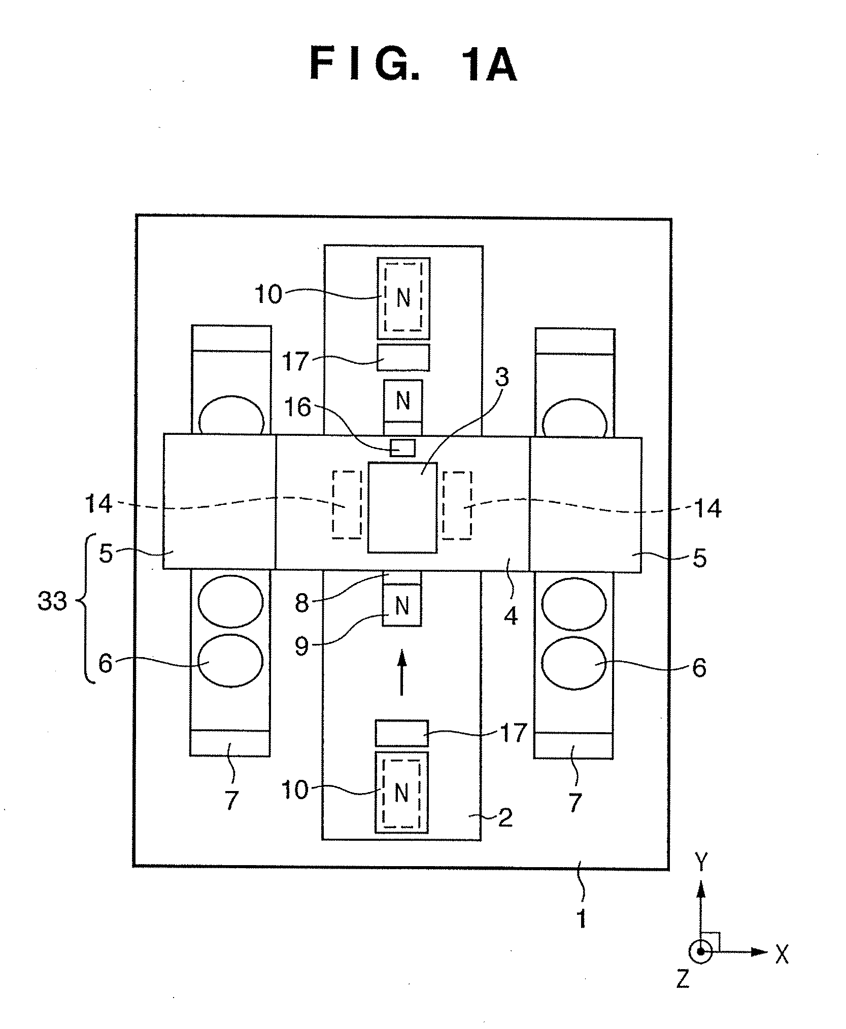
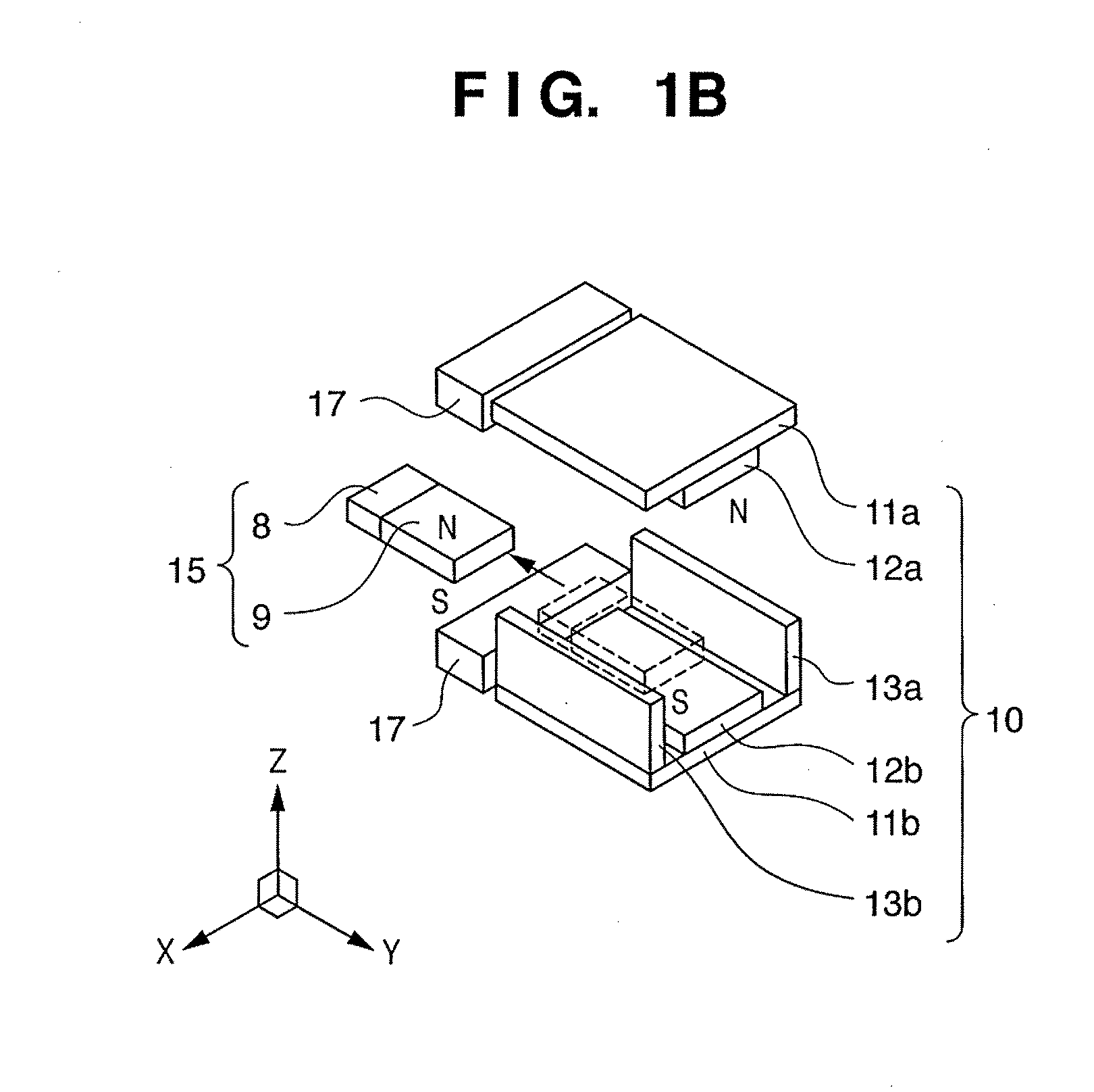
[0026]FIG. 1A is a plan view showing a stage apparatus according to the preferred first embodiment of the present invention. FIG. 1B is a perspective view showing a repulsion magnet unit (repulsive force generating unit).
[0027]In this stage apparatus, a base guide 2 is fixed on a main body base 1, and a stage 4 which mounts a processing object 3 is supported to be movable relative to the base guide 2 in one axial direction. Bearings 14 inserted between the upper surface of the base guide 2 and the lower surface of the stage 4 regulate the orientation of the stage 4. Since a semiconductor exposure apparatus is required to have high alignment accuracy, an air bearing is preferably used as the bearing 14. Linear motor movable elements 5 are fixed on the two sides of the stage 4. A linear motor stator 6 faces the linear motor movable element 5 in a noncontact manner, and is fixed on the main body base 1 via legs 7 at its two ends. The position of the stage 4 is measured by irradiating a...
second embodiment
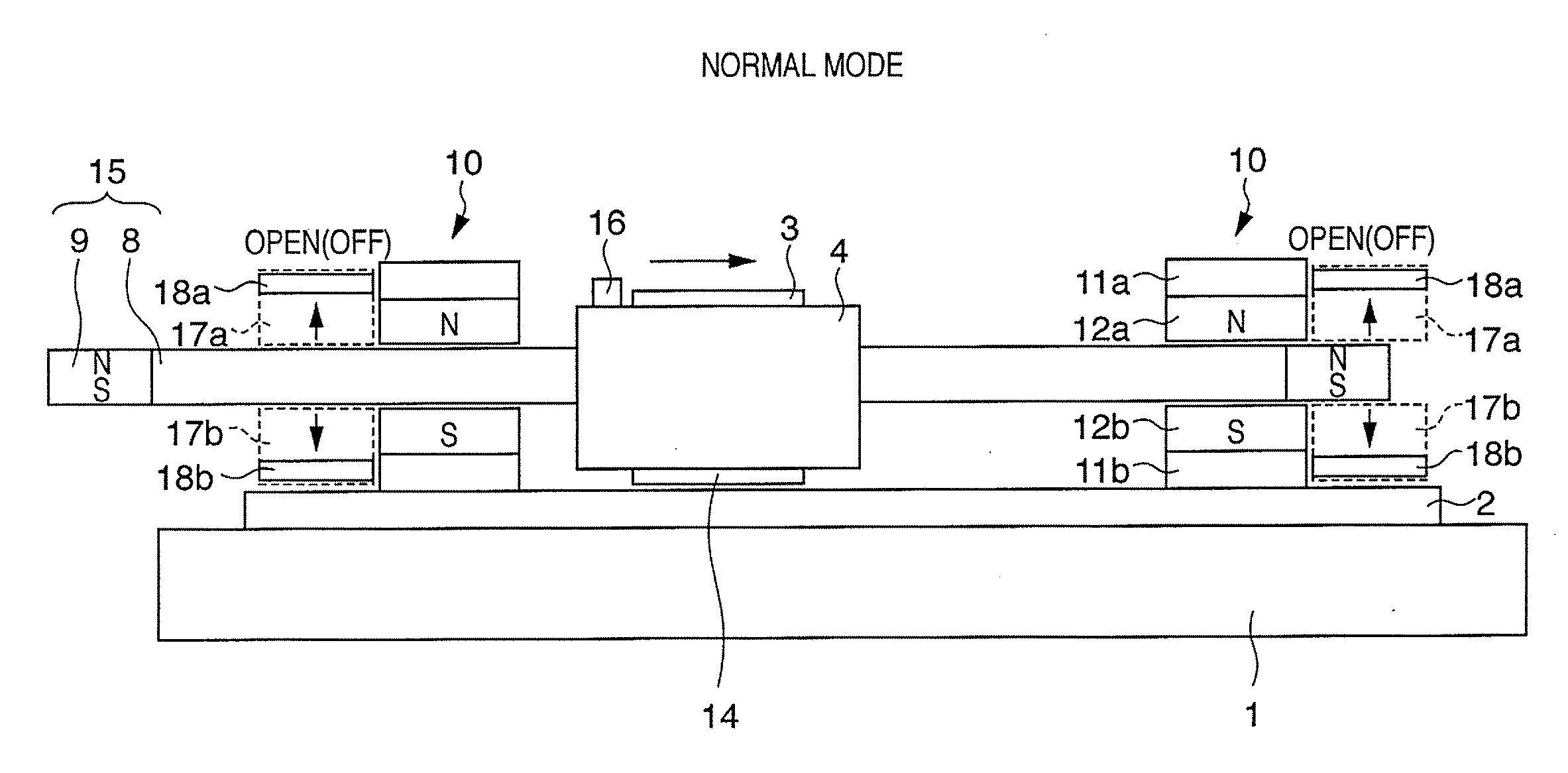
[0041]FIG. 3A is a side view showing a stage apparatus having nonmagnetic conductor driving units 17a and 17b in a normal mode according to the preferred second embodiment of the present invention. In the preferred second embodiment of the present invention, a movable magnet 9 is arranged outside a magnet repulsion stator 10. The nonmagnetic conductor driving units 17a and 17b hold nonmagnetic conductors 18a and 18b serving as eddy current generating members at positions away from the movable magnet 9 (the brake is open (OFF)). In this state, no eddy currents are generated even when the movable magnet 9 passes between the nonmagnetic conductors 18a and 18b. Since no brake force acts on a stage 4, repulsion magnet units provided at the two ends continue acceleration / deceleration driving.
[0042]FIG. 3B is a side view showing the stage apparatus having the nonmagnetic conductor driving units 17a and 17b in a brake mode executed in, for example, emergency stop. In the brake mode, the non...
third embodiment
[0047]FIG. 5A is a view showing nonmagnetic conductor driving units 17a and 17b in a normal mode according to the preferred third embodiment of the present invention. In the preferred third embodiment of the present invention, nonmagnetic conductors 18a and 18b are rotatably supported so that rotating motors 21a and 21b, belts 22a and 22b, and the like can rotationally drive them. In the normal mode, the nonmagnetic conductors 18a and 18b are kept standing vertically by rotating the motors (the brake is open (OFF)). The areas of surfaces of the nonmagnetic conductors 18a and 18b which face a movable magnet 9 are equal to their thicknesses. If thin plates are used as the nonmagnetic conductors 18a and 18b, the areas of their surfaces which face the movable magnet 9 become very small. Since the magnitudes of generated eddy currents also become very small, a brake force hardly acts on the movable magnet 9.
[0048]FIG. 5B is a view showing the nonmagnetic conductor driving units 17a and 1...
PUM
 Abstract
Description
Claims
Application Information