
Catalyst deterioration detecting system and catalyst deterioration detecting method of internal combustion engine

a technology of catalyst deterioration and detection system, which is applied in the direction of engines, machines/engines, mechanical equipment, etc., can solve the problems of reducing the oxygen storage capacity of the catalyst, and affecting the performance of the catalys

Inactive Publication Date: 2008-07-24
TOYOTA JIDOSHA KK
View PDF0 Cites 24 Cited by
  • Summary
  • Abstract
  • Description
  • Claims
  • Application Information

AI Technical Summary

Benefits of technology

[0014]It is found from experiments and research carried out by the inventors that a change in the catalyst temperature and a change in the oxygen storage capacity corresponding to the change in the catalyst temperature has a certain relationship, namely, the value of the oxygen storage capacity changes to a larger value as the catalyst temperature changes to a higher temperature level. It is also found that the change in the oxygen storage capacity corresponding to the change in the catalyst temperature is relatively large if the catalyst is free from poisoning, and is relatively small if the catalyst suffers poisoning. The catalyst deterioration detecting system and method of the internal combustion engine as described above are able to favorably determine the presence or absence of poisoning of the catalyst by utilizing the relationships as described above. It is thus possible to detect deterioration of the catalyst while distinguishing permanent deterioration to be detected from temporary deterioration due to poisoning of the catalyst.
[0028]The catalyst deterioration detecting system or method according to this invention provides an excellent effect that it can detect permanent deterioration of a catalyst while distinguishing it from temporary deterioration due to poisoning.

Problems solved by technology

Where such a fuel is supplied to the engine, poisoning (e.g., S (sulfur) poisoning) may occur to the catalyst, namely, the poisoning substance may be accumulated in the catalyst, resulting in reduction of the performance of the catalyst.
If the poisoning occurs, catalytic reactions to adsorb and release oxygen are impeded or hampered, and the oxygen storage capacity of the catalyst is reduced.
Thus, unless a controller of the engine detects catalyst deterioration while distinguishing from temporary deterioration due to poisoning, there is a possibility of erroneously determining that a catalyst whose exhaust treatment performance is temporarily reduced due to poisoning is deteriorated even though this catalyst should be regarded as being normal.
No suitable system has been found which effectively utilizes this fact when detecting catalyst deterioration, and is able to detect deterioration of a catalyst while distinguishing permanent deterioration from temporary deterioration due to poisoning.

Method used


Image

  • Catalyst deterioration detecting system and catalyst deterioration detecting method of internal combustion engine
  • Catalyst deterioration detecting system and catalyst deterioration detecting method of internal combustion engine
  • Catalyst deterioration detecting system and catalyst deterioration detecting method of internal combustion engine

Examples


first embodiment

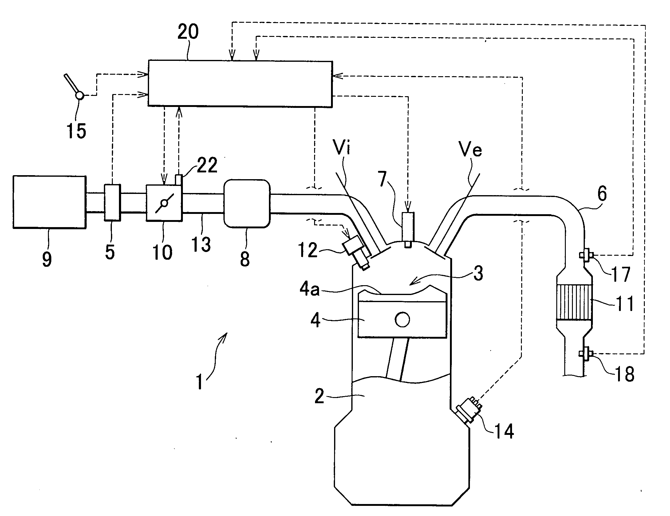
[0074]In the following, detection of catalyst poisoning will be explained with reference to FIG. 6. The ECU 20 repeatedly executes the routine of the process illustrated in FIG. 6 at certain time intervals.

[0075]Initially, it is determined in step S101 whether preconditions for measurement of the oxygen storage capacity along with execution of the active air / fuel ratio control are satisfied. The preconditions, which are similar to the above-described preconditions for execution of catalyst deterioration detection, are satisfied if the engine 1 is in normal (or steady-state) operating conditions and the catalyst temperature is in a certain activation temperature range. If the conditions are not satisfied, the process of FIG. 6 is finished. If the conditions are satisfied, on the other hand, the ECU 20 proceeds to step S102.

[0076]In step S102, an estimated value of the catalyst temperature Tc is acquired. In step S103, it is determined whether the estimated value of the catalyst temp...

third embodiment

[0090]In the third embodiment, therefore, poisoning of the catalyst is detected from the relationship between a change in the rich amplitude Ar and a change in the oxygen storage capacity OSC corresponding to the change in the rich amplitude Ar. More specifically, poisoning of the catalyst is detected based on the amount of change of the oxygen storage capacity between at least two points of rich amplitudes Ar.

[0091]Referring to FIG. 8, for example, when the rich amplitude Ar is equal to a relatively small first amplitude Ara, the same oxygen storage capacity OSCa is obtained in the case where the catalyst suffer poisoning and the case where the catalyst is free from poisoning. On the other hand, when the rich amplitude Ar is equal to a relatively large second amplitude Arb, the oxygen storage capacity is equal to OSCb1 where the catalyst is free from poisoning, while it is equal to OSCb2 that is smaller than OSCb1 where the catalyst suffers poisoning. Thus, the presence or absence ...


PUM


Abstract

A catalyst deterioration detecting system of an internal combustion engine includes a measuring unit that measures the oxygen storage capacity of a catalyst, a detector that detects or estimates the temperature of the catalyst, and a detector that detects poisoning of the catalyst based on the relationship between a change in the catalyst temperature and a change in the oxygen storage capacity corresponding to the change in the catalyst temperature. The change in the oxygen storage capacity corresponding to the change in the catalyst temperature varies depending on the presence or absence of poisoning of the catalyst. Thus, the catalyst deterioration detecting system is able to favorably detect poisoning of the catalyst by utilizing this relationship, and distinguish temporary deterioration due to catalyst poisoning from permanent deterioration. A method of detecting deterioration of the catalyst is also provided.

Description

INCORPORATION BY REFERENCE[0001]The disclosure of Japanese Patent Application No. 2007-011247 filed on Jan. 22, 2007, including the specification, drawings and abstract, is incorporated herein by reference in its entirety.BACKGROUND OF THE INVENTION[0002]1. Field of the Invention[0003]The invention relates to a catalyst deterioration detecting system that detects deterioration of a catalyst disposed in an exhaust passage of an internal combustion engine, and also relates to a catalyst deterioration detecting method.[0004]2. Description of the Related Art[0005]Generally, a catalyst is disposed in an exhaust passage of an internal combustion engine so as to treat or clean exhaust gas. One type of the catalyst is, for example, a three-way catalyst that has an O2 storage function of adsorbing and releasing oxygen depending on the air / fuel ratio of exhaust gas entering the catalyst. More specifically, the catalyst adsorbs and stores excessive oxygen present in the exhaust gas when the ai...

Claims


Application Information

Patent Timeline
IPC IPC(8): F01N3/00F01N3/18F01N3/08
CPCF01N11/002Y02T10/47F01N2550/02F01N11/007Y02T10/40
Inventor KIDOKORO, TORUKIMURA, KOICHIKITAURA, KOICHI
Owner TOYOTA JIDOSHA KK
Learn More