Magnetic Levitation Weight Reduction Structure for a Vertical Wind Turbine Generator

a technology of wind turbine generator and magnetic levitation, which is applied in the direction of electric generator control, machines/engines, magnetic bodies, etc., can solve the problems of reducing the efficiency and speed of the fixed shaft supporting the hub, and achieve the effect of reducing the burden, reducing the resistance, and promoting the revolving efficiency and speed of the axl

Inactive Publication Date: 2008-07-24
HU SUEY YUEH
View PDF12 Cites 49 Cited by
  • Summary
  • Abstract
  • Description
  • Claims
  • Application Information

AI Technical Summary

Benefits of technology

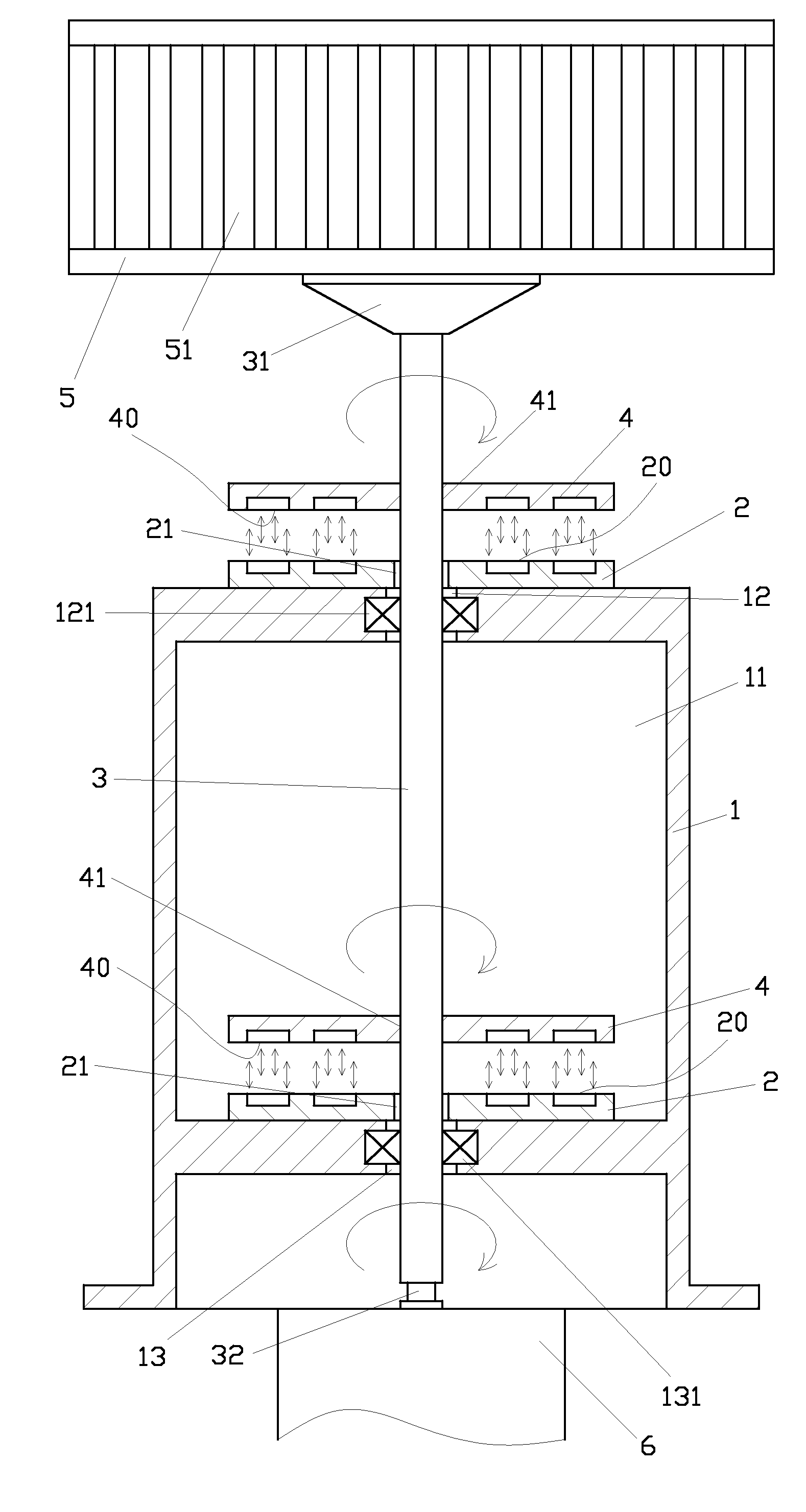
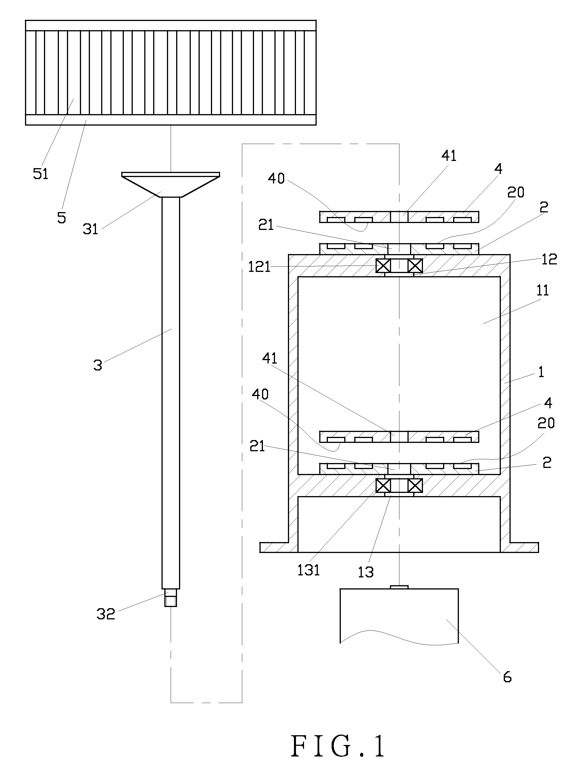
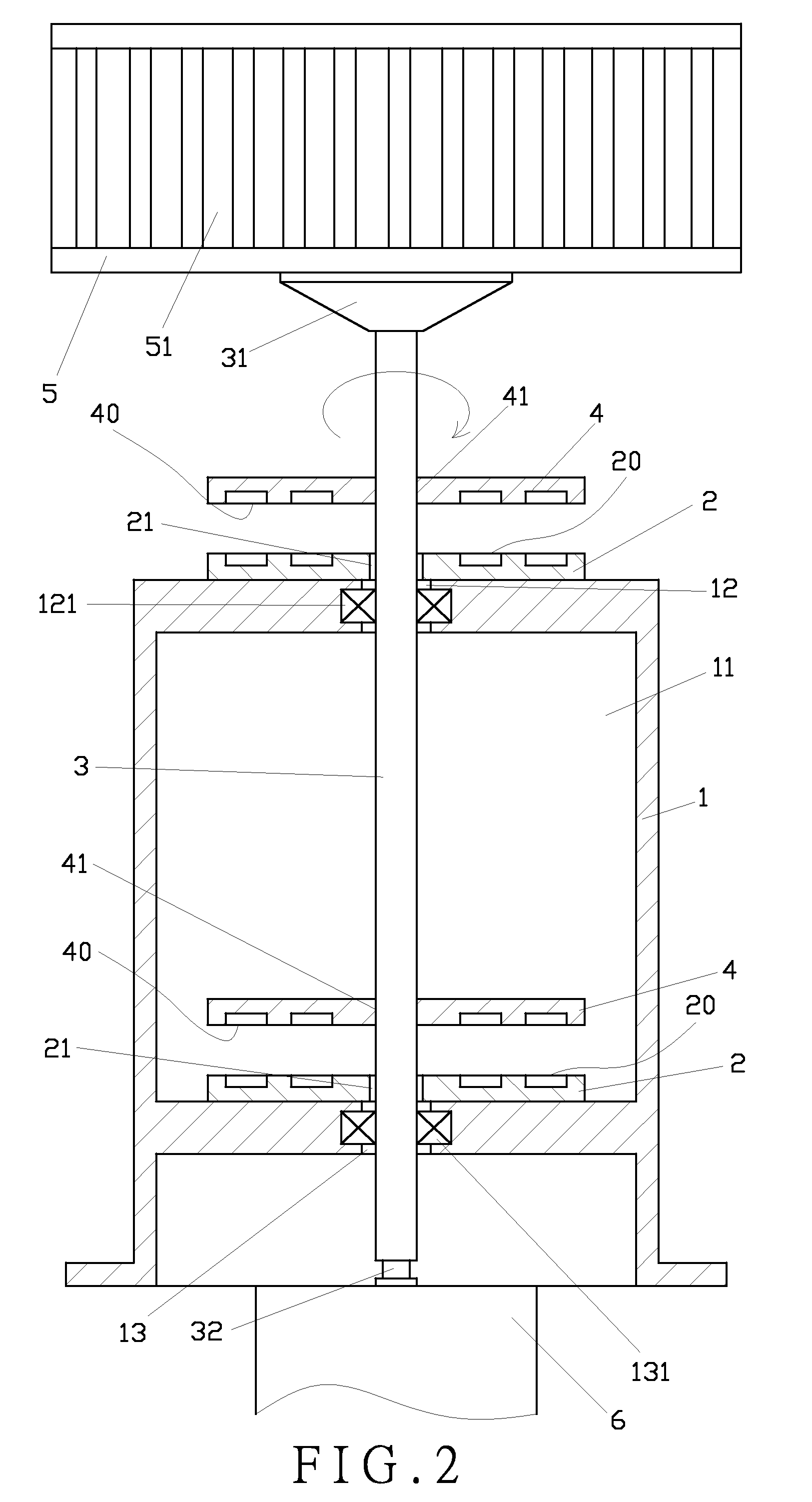
[0005]The primary purpose of the present invention is to provide a magnetic levitation weight reduction structure for a vertical wind turbine generator by having repulsive force created due to same magnetic pole thus to alleviate support weight sustained by the axle and minimize operating noise of the turbine.
[0007]A repulsive force created by the same magnetic pole of the fixed permanent magnet and the revolving permanent alleviates the burden while the axle drives the blade hub to revolve, offsets the resistance by friction of the generator connected to the axle, promotes the revolving efficiency and speed of the axle, and reduces the noise created by friction against the generator.

Problems solved by technology

However, as the size and weight ratio of the hub varies, the revolving efficiency and speed of the fixed shaft supporting the hub are compromised due to the weight ratio, resulting in noise due to friction.

Method used


Image

  • Magnetic Levitation Weight Reduction Structure for a Vertical Wind Turbine Generator
  • Magnetic Levitation Weight Reduction Structure for a Vertical Wind Turbine Generator
  • Magnetic Levitation Weight Reduction Structure for a Vertical Wind Turbine Generator

Examples


second embodiment

[0024]In the present invention as illustrated in FIG. 4, a fixed permanent magnet (2A) is fixed to a frame (1A). The fixed permanent magnet (2A) has a first repulsive surface (20A), a circular flat portion (21A) and an inclined portion (22A) extending from the circumference of the flat portion (21A). An axle (3A) is inserted through the frame (1A) and the fixed permanent magnet (2A). A revolving permanent magnet (4A) fixed to the axle (3A) has a second repulsive surface (40A), a flat portion (41A) and an inclined portion (42A) extending from the circumference of the flat portion (41A). Both the first repulsive surface (20A) of the fixed permanent magnet (2A) and the second repulsive surface (40A) of the revolving permanent magnet (4A) are assembled in the shape of a bowl. A repulsive force is created by the same magnetic pole of the fixed permanent magnet (2A) and the revolving permanent magnet (4A). When the blades are revolving for being subject to wind velocity, a repulsive force...

third embodiment

[0025]FIG. 5 shows the present invention. A fixed permanent magnet (2B) is fixed to a frame (1B). The fixed permanent magnet (2B) has a first repulsive surface (20B), a flat portion (21B) and a flange (22B) vertically extending from the circumference of the flat portion (21B). An axle (3B) penetrates through the frame (1B) and the fixed permanent magnet (2B). A revolving permanent magnet (4B) fixed to the axle (3B) has a second repulsive surface (40B), a flat portion (41B) and a flange (42B) vertically extending from the circumference of the flat portion (41B). Accordingly, the configuration between the fixed permanent magnet (2B) and the revolving permanent magnet (4B) indicates a reverse U-like shape; and a repulsive force is relatively produced by the same magnetic pole of the permanent magnet (2B) and the revolving permanent magnet (4B). Once the blades revolve for being subject to wind velocity, a repulsive force is relatively created between the vertical flange (22B) and the v...


PUM


Abstract

A magnetic levitation weight reduction structure for a vertical wind turbine generator includes a frame, a fixed permanent magnet, an axle, a revolving permanent magnet, a blade hub, and a generator. The fixed permanent magnet fixed to the frame has a first repulsive surface. The axle is connected to the frame. The revolving permanent magnet fixed to the axle has a second repulsive surface in relation to the first repulsive surface of the fixed permanent magnet. Both the first and the second repulsive surfaces repel with each other. The blade hub and the generator are connected to the axle. When the revolving permanent magnet is rotated, the axle functions as a balance center.

Description

BACKGROUND OF THE INVENTION[0001](a) Field of the Invention[0002]The present invention relates to a magnetic levitation weight reduction structure adapted to a vertical wind turbine generator, and more particularly, to one that is capable of producing repulsive force from the same magnetic pole of a fixed permanent magnet and a revolving permanent magnet thus to drive a hub to revolve with reduced support weight while upgrading the turning efficiency of the hub and increasing its revolving speed.[0003](b) Description of the Prior Art[0004]A conventional wind turbine generator comprises a base, a turbine hub, a linking shaft, and a generator. The base includes a locating portion. The turbine hub is disposed with multiple blades and a fixed shaft at the center. The fixed shaft corresponds to the locating portion of the base to revolve. The fixed shaft is provided with a gear set. The linking shaft corresponds to the gear set and turns around when the gear set is engaged with the linki...

Claims


Application Information

Patent Timeline
Patent Type & Authority Applications(United States)
IPC IPC(8): H02K7/09F03D9/00
CPCF03D11/0008F05B2240/211F05B2240/511Y02E10/725F16C2300/14F16C2300/34Y02E10/722F16C39/066F03D80/70F16C2360/31H01F7/0236Y02E10/72
Inventor HU, SUEY-YUEH
Owner HU SUEY YUEH
Why Eureka
Try Eureka