Filter circuit for reducing EMI of differential signal

Inactive Publication Date: 2008-07-24
ASUSTEK COMPUTER INC
View PDF5 Cites 7 Cited by
  • Summary
  • Abstract
  • Description
  • Claims
  • Application Information

AI Technical Summary

Benefits of technology

[0009]It is therefore an objective of the invention to provide a filter circuit employing passive component sets in cooperative with circuit designs to improv

Problems solved by technology

The signal-transmission-speed of the electrical devices is faster and faster, and therefore electro magnetic interference (EMI), which is produced by the electrical components disposed in the electrical devices, is more and more serious to affect the normal operation of the electrical devices.
However, in the combined anti-EMI filters, the capacitors and the inductors are easily affected at high frequency by the distributed parameters even to cause resonance then to reduce the performance

Method used


Image

  • Filter circuit for reducing EMI of differential signal
  • Filter circuit for reducing EMI of differential signal
  • Filter circuit for reducing EMI of differential signal

Examples


Example

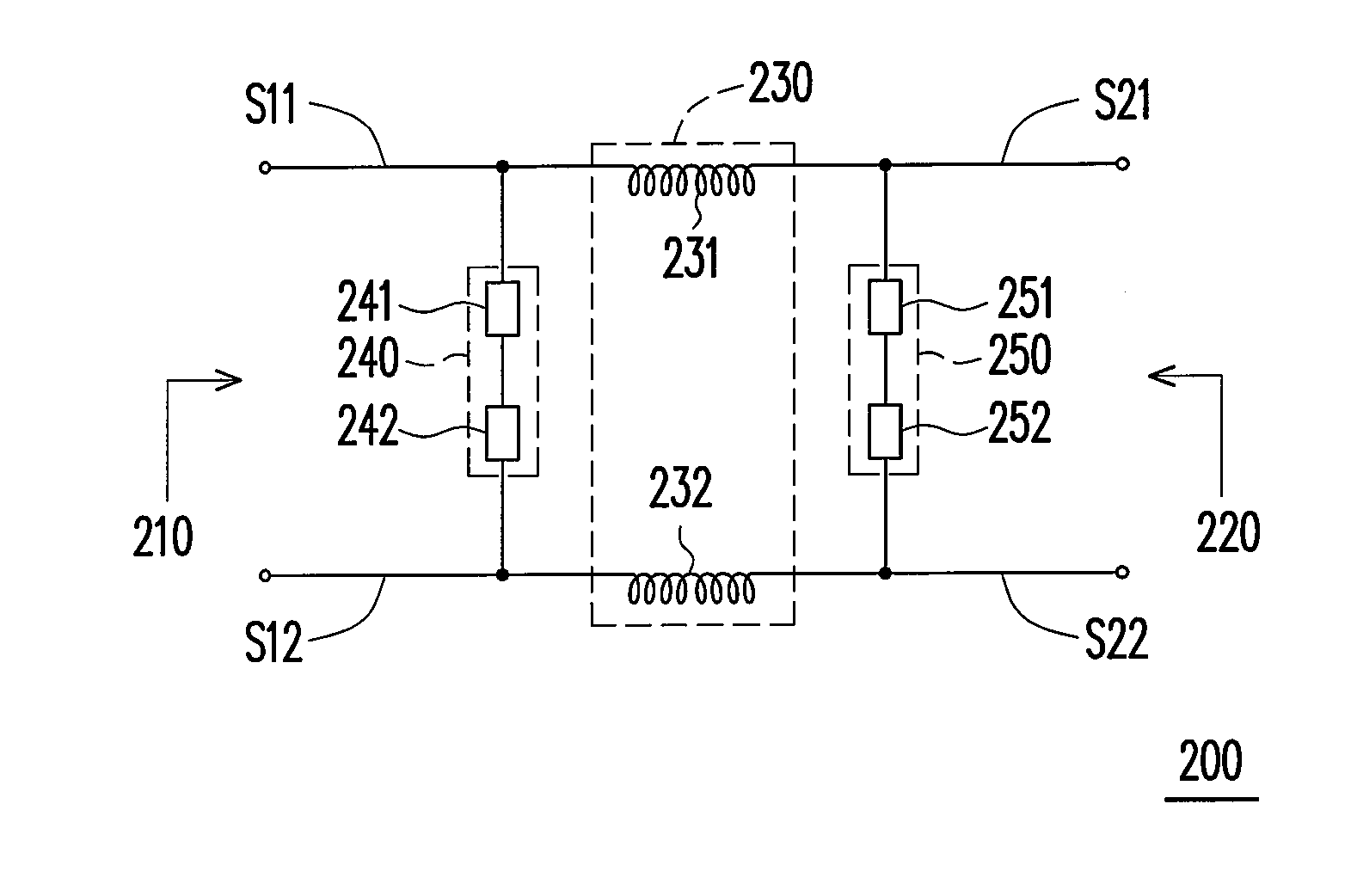
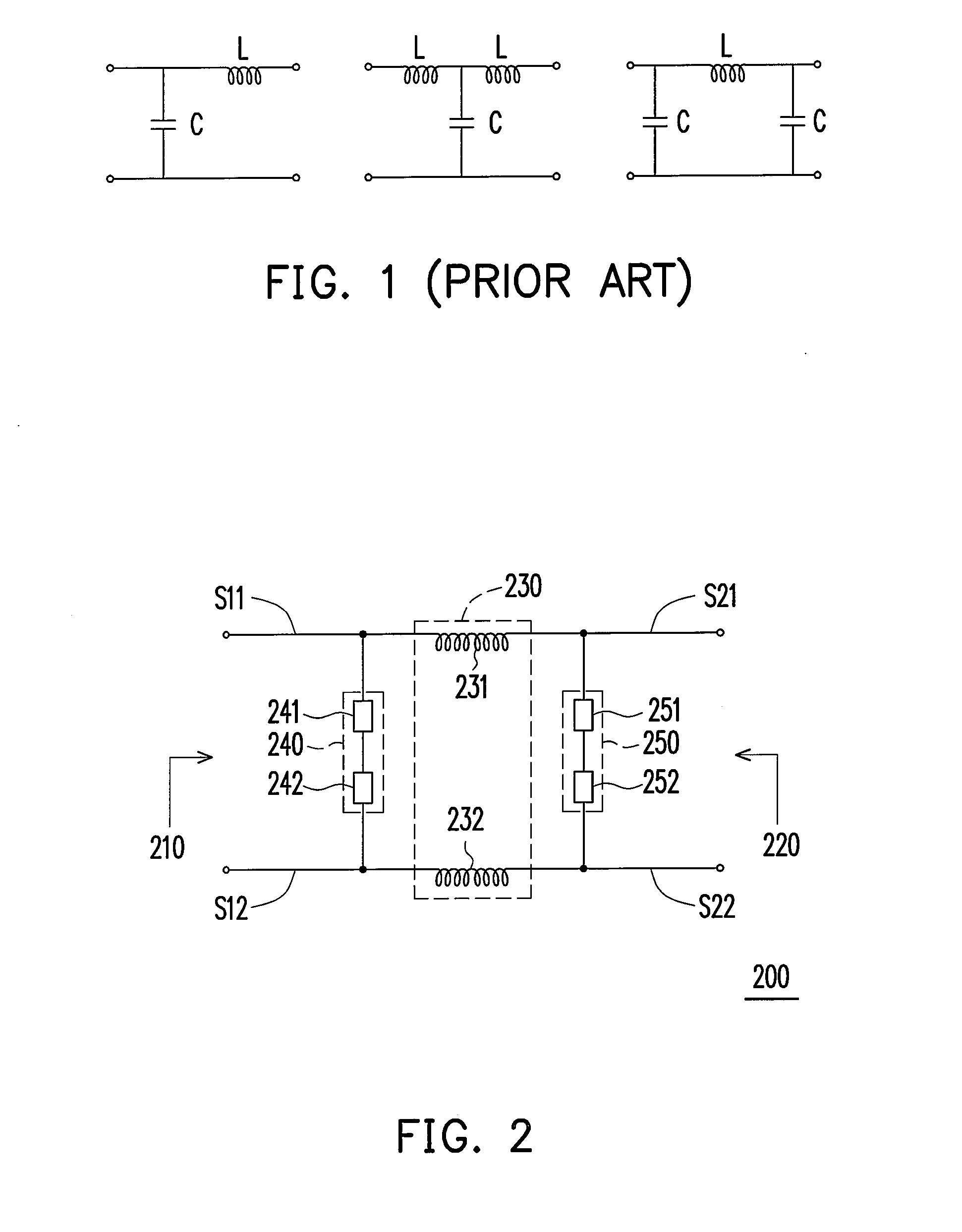
[0021]FIG. 2 is a configuration diagram showing a filter circuit 200 according to a preferred embodiment of the invention. In FIG. 2, the filter circuit 200 includes a passive component set 230, a passive component set 240, and a passive component set 250. The passive component set 230 has input / output sides 210 and 220 for receiving or outputting a differential signal, respectively. Furthermore, the input / output sides both have a positive signal end, such as S11 and S21, and a negative signal end, such as S12 and S22. The positive signal end S11 and the negative signal end S12 are coupled to each other via the passive component set 240. The positive signal end S21 and the negative signal end S22 are coupled to each other via the passive component set 250.

[0022]The passive component set 230 may include passive components 231 and 232. The first end and the second end of the passive component 231 are correspondingly coupled to the positive signal ends S11 and S21, and the first end an...


PUM


Abstract

A filter circuit for reducing electro magnetic interference (EMI) of a differential signal is disclosed. The circuit includes a first passive component set, a second passive component set, and a third passive component set. The first passive component set has a first input/output side and a second input/output side. The second passive component set is disposed between a positive signal end and a negative signal end of the first input/output side, and the third passive component set is disposed between a positive signal end and a negative signal end of the second input/output side. According to the circuit of the present invention, EMI of the differential signal can be reduced and signal-transmission-speed may not be reduced.

Description

CROSS-REFERENCE TO RELATED APPLICATION[0001]This application claims the priority benefit of Taiwan application serial no. 96101887, filed on Jan. 18, 2007. The entirety of the above-mentioned patent application is hereby incorporated by reference herein and made a part of this specification.BACKGROUND OF THE INVENTION[0002]1. Field of the Invention[0003]The invention relates to a signal processing device and, more particularly, to a filter circuit for reducing electro magnetic interference (EMI) of a differential signal.[0004]2. Description of the Related Art[0005]In the valuation standards of all kinds of electrical devices, electro magnetic compatibility (EMC) is a key quality indicator for a personal computer, a television, audio equipment, and so on. In the modern developed countries, the valuation reports on EMC are paid more and more attention to. The signal-transmission-speed of the electrical devices is faster and faster, and therefore electro magnetic interference (EMI), wh...

Claims


Application Information

Patent Timeline
IPC IPC(8): H03H7/06
CPCH03H1/0007H03H7/0115H03H2001/0057H03H7/1758H03H7/425H03H7/06
Inventor CHIANG, CHIN-CHUN
Owner ASUSTEK COMPUTER INC
Why Eureka
Try Eureka