Method and apparatus for network fault detection and protection switching using optical switches with integrated power detectors

a technology of optical switches and power detectors, applied in multiplex communication, transmission monitoring, instruments, etc., can solve the problems of slow fault recovery time, significant number of disruptions and outages, and high cost of downtime for carriers, so as to reduce network fault recovery time

Active Publication Date: 2008-07-24
POLATIS PHOTONICS INC
View PDF8 Cites 57 Cited by
  • Summary
  • Abstract
  • Description
  • Claims
  • Application Information

AI Technical Summary

Benefits of technology

[0003]An example embodiment of the present invention is a method, and corresponding apparatus, for switching optical communications paths by detecting optical power of an optical signal at optical switches coupled via optical communications paths. The example embodiment further includes causing at least one optical communications path between a first optical switch and second optical switch to switch to an alternative optical communications path, in part, through physical layer triggering in an event optical power at at least one of the first or second optical switches falls below a threshold level. Switches autonomously switching in response to a physical layer trigger results in reduced network fault recovery times.

Problems solved by technology

Fiber cuts, equipment faults and degradations cause a significant number of disruptions and outages.
Often, fault recovery times are slow as the network components (e.g., switches and network administrators) communicate to switch around equipment failures.
As businesses and consumers become increasingly intolerant of network failures, downtime can be very expensive to carriers due to both lost revenue and tarnished reputations.

Method used


Image

  • Method and apparatus for network fault detection and protection switching using optical switches with integrated power detectors
  • Method and apparatus for network fault detection and protection switching using optical switches with integrated power detectors
  • Method and apparatus for network fault detection and protection switching using optical switches with integrated power detectors

Examples


Embodiment Construction

[0018]A description of example embodiments of the invention follows.

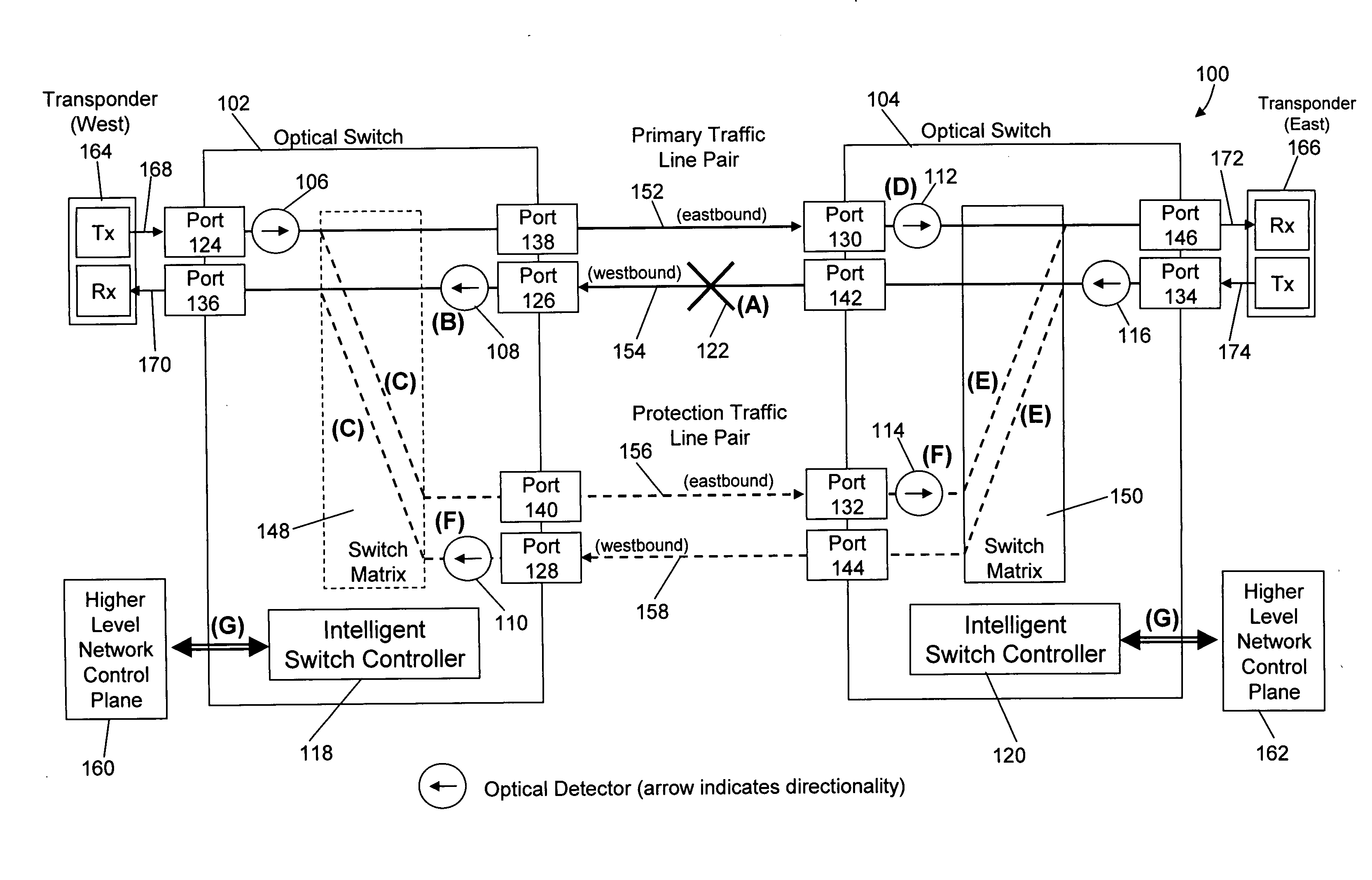
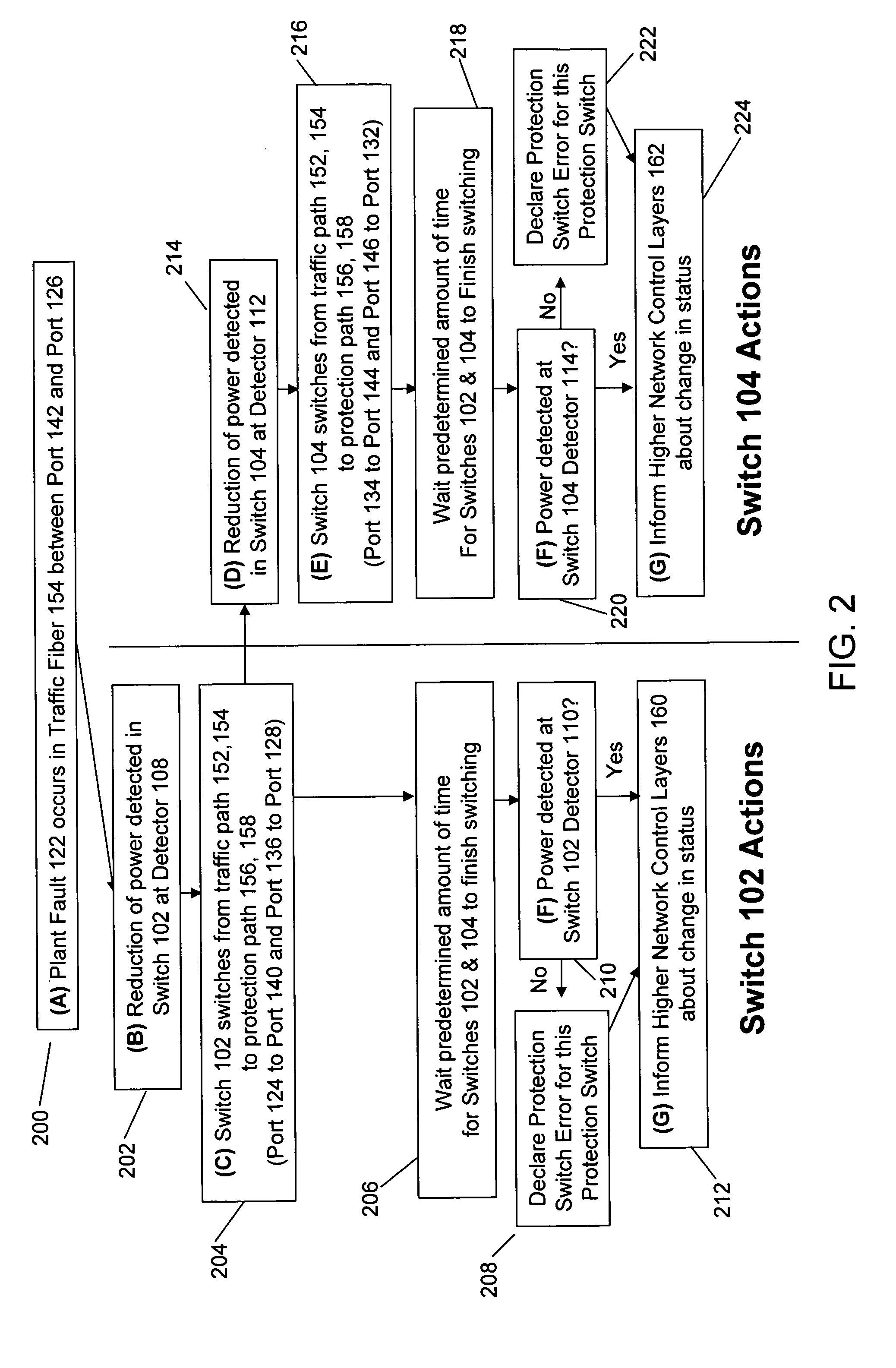
[0019]Integrating fault detection into optical switching at the physical layer can greatly increase the speed of protection switching. Existing protection switching systems usually involves higher level communications or signaling between nodes in the network using complex framed overhead channels or packet communications. Embodiments of this invention increase the speed of fault detection and network protection switching by having intelligent optical switches with optical power detectors that can locally detect faults in the optical line. A network fault typically results in the loss or reduction of optical power. The intelligent optical switch autonomously switches from a traffic fiber pair to protection fiber pairs when a fault is detected. The switching results in other intelligent optical switches also detecting a loss or reduction in optical power, causing those switches to autonomously switch to protection fi...


PUM


Abstract

Current network switching architectures require communication with a higher level network control plane, which can be slow to reroute communications, resulting in unacceptable losses of communications for customers. Examples embodiments of the present invention reroute communications faster detecting optical power of an optical signal at optical switches coupled via optical communication paths, and causing at least one optical communication path between a first optical switch and second optical switch to switch to an alternative optical communication path, in part, through physical layer triggering in an event optical power at at least one of the first or second optical switches falls below a threshold level. Switching in response to physical layer triggering may result in reduced switching times and, consequently, faster restoration of communications to customers after a network fault interruption.

Description

RELATED APPLICATION(S)[0001]This application claims the benefit of U.S. Provisional Application No. 60 / 876,348, filed on Dec. 20, 2006. The entire teachings of the above application is incorporated herein by reference.BACKGROUND OF THE INVENTION[0002]Fiber cuts, equipment faults and degradations cause a significant number of disruptions and outages. Often, fault recovery times are slow as the network components (e.g., switches and network administrators) communicate to switch around equipment failures. As businesses and consumers become increasingly intolerant of network failures, downtime can be very expensive to carriers due to both lost revenue and tarnished reputations. As a result, carriers continually search for better ways to protect networks against such fiber faults and reduce costs by more efficient use of protection bandwidth.SUMMARY OF THE INVENTION[0003]An example embodiment of the present invention is a method, and corresponding apparatus, for switching optical communi...

Claims


Application Information

Patent Timeline
Patent Type & Authority Applications(United States)
IPC IPC(8): H04B10/00H04J14/00H04B10/07H04B10/032H04B10/27
CPCH04L1/22H04Q2011/0083H04Q2011/0081H04Q11/0062H04B10/032H04B10/07H04B10/27
Inventor JENSEN, RICHARD A.
Owner POLATIS PHOTONICS INC
Why Eureka
Try Eureka