Pump oil mister with improved service life

a technology of pump oil mister and service life, which is applied in the direction of manual lubrication, liquid fuel engines, machines/engines, etc., can solve the problems of increasing maintenance requirements, serious harm to the environment, and undesirable heat generation within the bearings and adjacent to the pump sha

Inactive Publication Date: 2008-07-24
ENVIRONAMICS
View PDF2 Cites 14 Cited by
  • Summary
  • Abstract
  • Description
  • Claims
  • Application Information

AI Technical Summary

Problems solved by technology

Environmentally hazardous fluids such as acids, oils, and toxins, which can cause serious harm to the environment often need to be pumped throughout fluid flow systems from one location to another.
This results in undesirable heat generation within the bearings and adjacent the pump shaft, this heat generation being caused by the friction created by the bearing balls continually passing through the lubricating oil.
Such heat generation increases maintenance requirements and reduces the operating life of the bearings.
Because the bearing balls circumferentially rotate or roll around the pump shaft via these raceways, the presence of such contaminants therein causes increased wear of the bearings and thus additional maintenance.
Such plowing of the hoods generates undesirable heat within the lubrication chamber and requires the bearings to run at an increased temperature thereby resulting in increased maintenance requirements.
Additionally, as a result of the hoods of the '676 dispenser picking up the lubricating oil and subsequently delivering it throughout the chamber, dirt and other contaminants such as rust, carbonized particles, etc. are sometimes directed toward the bearings along with the picked up lubricating oil, this also increasing maintenance requirements.
As discussed above, it is undesirable for the bearing balls to be submerged within the lubricating fluid at the lower end of the lubrication chamber due to the resulting heat generation.

Method used


Image

  • Pump oil mister with improved service life
  • Pump oil mister with improved service life
  • Pump oil mister with improved service life

Examples


Embodiment Construction

[0033]Referring now more particularly to the accompanying drawings in which like reference numerals indicate like parts throughout the several views.

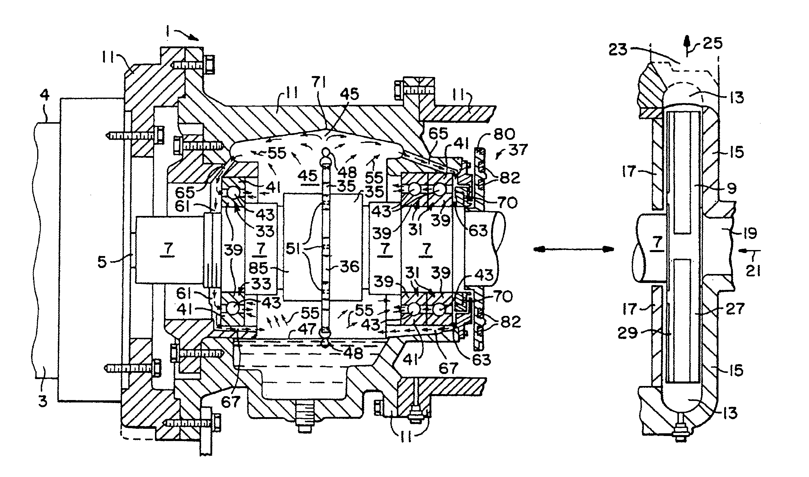
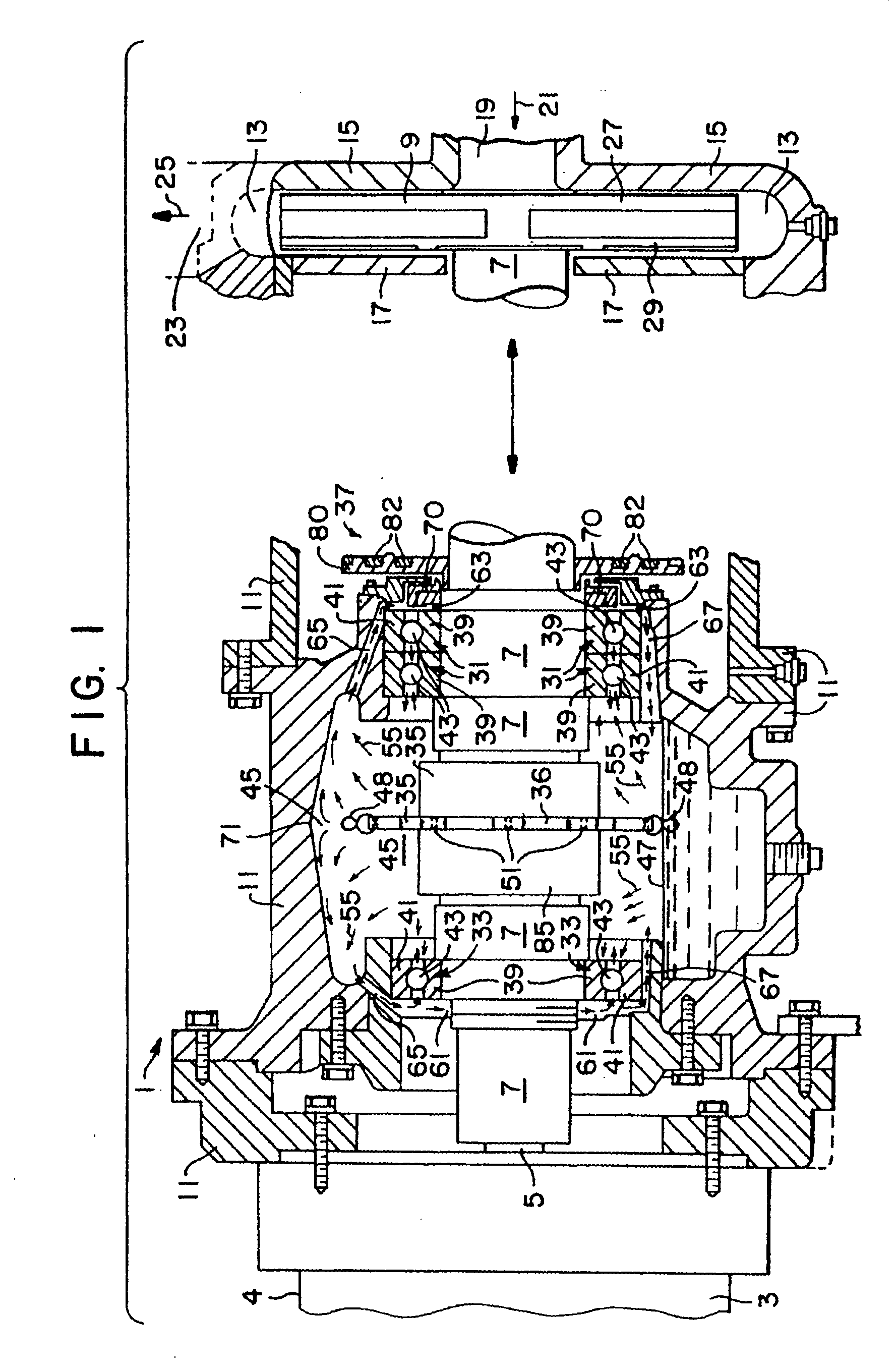
[0034]FIG. 1 is a side elevational partial cross-sectional view of a centrifugal environmentally sealed pump including a shaft bearing lubrication system according to the first embodiment of this invention. The pump and lubrication system according to this embodiment are illustrated in FIG. 1 cross-sectionally except for pump motor 3, pump shaft 7, impeller 9, and dispenser 35 which are shown in a side elevational nature. Pump 1 is a hermetically sealed pump preferably used for pumping hazardous fluids such as acids, oils, and the like, but, of course, may also be used for pumping conventional non-hazardous materials.

[0035]Pump 1 includes electric motor 3 hermetically sealed within metallic motor housing 4. Motor 3 includes drive shaft 5 coupled at one longitudinal end to pump shaft 7. Pump shaft 7 is affixed at one end to fluid pumping...


PUM

PropertyMeasurementUnit
centrifugal forceaaaaaaaaaa
diameteraaaaaaaaaa
outer diameteraaaaaaaaaa

Abstract

A centrifugal environmentally safe pump including a motor driven pump shaft having a fluid pumping impeller affixed thereto. A plurality of annular shaft supporting bearing assemblies are disposed along the shaft adjacent a lubrication chamber, the lubrication chamber housing lubrication fluid (e.g. oil) maintained at a level below rotating portions of the bearing assemblies so as to maintain a low operating temperature within the chamber and adjacent the bearings. A lubricating fluid dispenser having a thin-profile, disc-shaped portion is affixed to the pump shaft within the lubrication chamber for rotation along with the shaft. A plurality of wire-like fluid contacting members are loosely connected along the outer periphery of the disc-shaped portion through respective bearing sleeves, the wire members for dipping into the lubricating fluid when the pump shaft is rotating thereby dispersing or misting the fluid throughout the chamber.

Description

[0001]This application claims the domestic priority benefit of U.S. Provisional Application No. 60 / 818,531 filed Jul. 7, 2006, the disclosure of which is hereby incorporated by reference.FIELD OF THE INVENTION[0002]This invention relates to a bearing lubrication system for a pump. More particularly, this invention relates to a bearing lubrication system disposed within a pump for lubricating bearings rotatably supporting the pump shaft.BACKGROUND OF THE INVENTION[0003]Environmentally hazardous fluids such as acids, oils, and toxins, which can cause serious harm to the environment often need to be pumped throughout fluid flow systems from one location to another. Centrifugal pumps generally including a motor driven impeller affixed to a pump shaft are typically utilized in pumping such fluids. The pump shafts of such pumps are typically rotatably supported against radial movement and vibration by conventional pump shaft bearings (e.g. ball bearings). These bearings must be continuall...

Claims


Application Information

Patent Timeline
Patent Type & Authority Applications(United States)
IPC IPC(8): F04B53/18F04D29/06F16N7/00
CPCF04D29/049Y10T29/49243F16N7/26F04D29/06
Inventor ROCKWOOD, ROBERT E.
Owner ENVIRONAMICS
Why Eureka
Try Eureka