Axial flow fan

a technology of axial flow fan and axial flow, which is applied in the direction of positive displacement liquid engine, piston pump, liquid fuel engine, etc., can solve the problems of insufficient mounting space for electronic components, affecting the performance of electronic components and the operation of the motor, and inability to ensure the mounting space of electronic components is too small, so as to increase the area of the circuit board and increase the number of electronic components.

Inactive Publication Date: 2008-07-24
NIPPON DENSAN CORP
View PDF3 Cites 18 Cited by
  • Summary
  • Abstract
  • Description
  • Claims
  • Application Information

AI Technical Summary

Benefits of technology

[0014]With the structure of the axial flow fan according to preferred embodiments of the present invention, the area of the circuit board can be increased, and thus an increased number of electronic components can be mounted thereon.

Problems solved by technology

This causes increase in the amount of rise in temperature of electronic components on the circuit board or coils of the armature inside the motor, which may affect the performance of the electronic components and the operation of the motor.
With the sizes of the conventional circuit boards, however, it is not possible to ensure sufficient space for mounting electronic components to be necessitated in responding to the future demand, for the mounting space for the electronic components is too small.

Method used


Image

  • Axial flow fan
  • Axial flow fan
  • Axial flow fan

Examples


first preferred embodiment

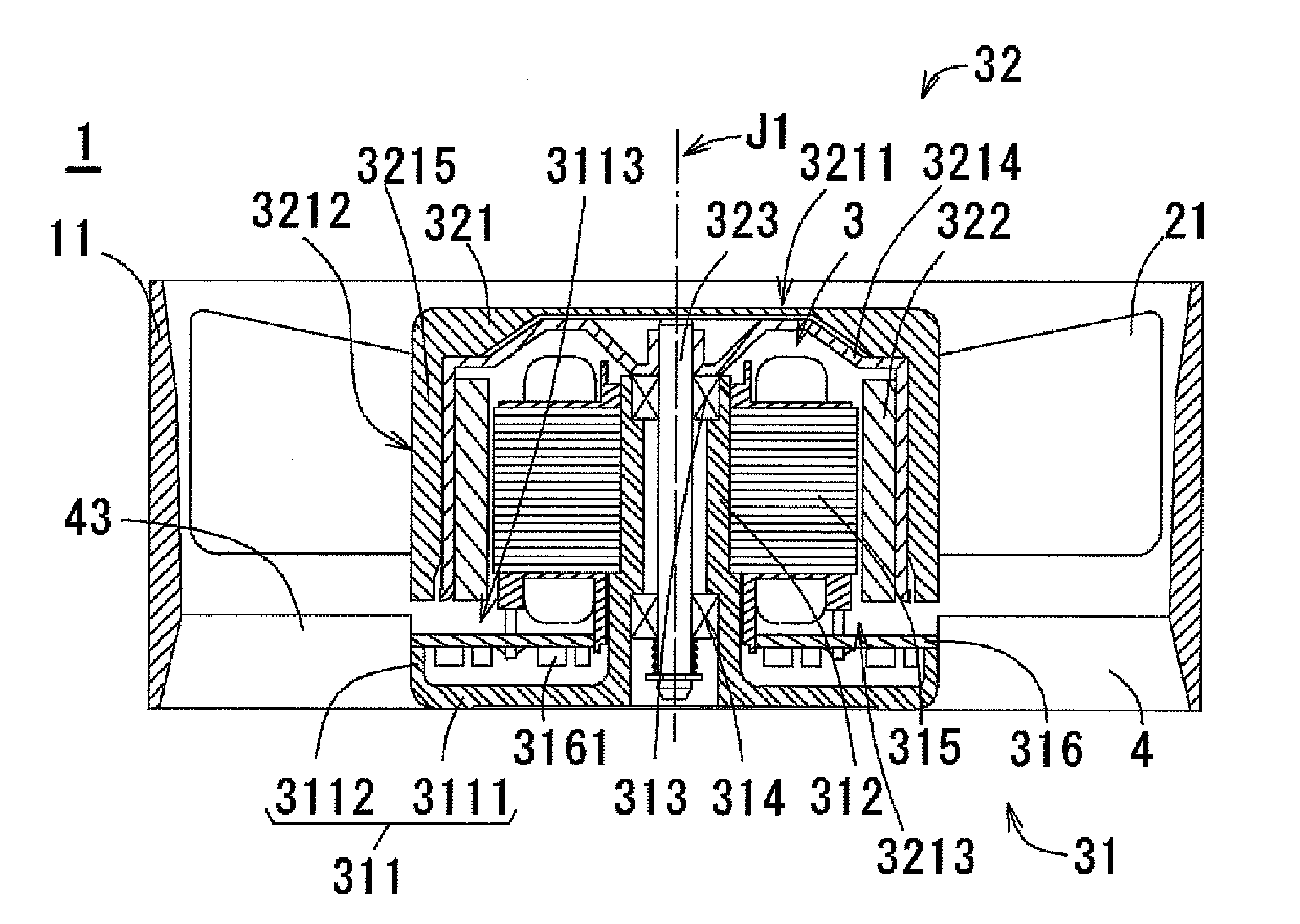
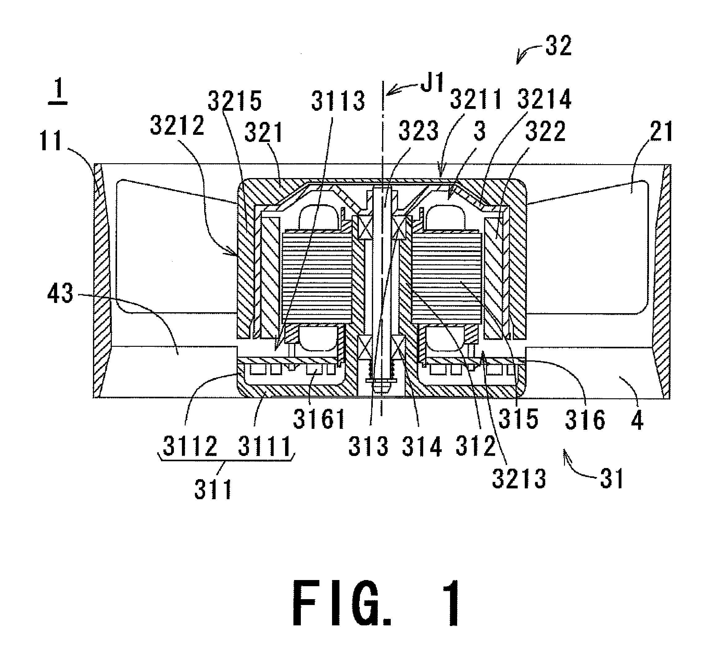
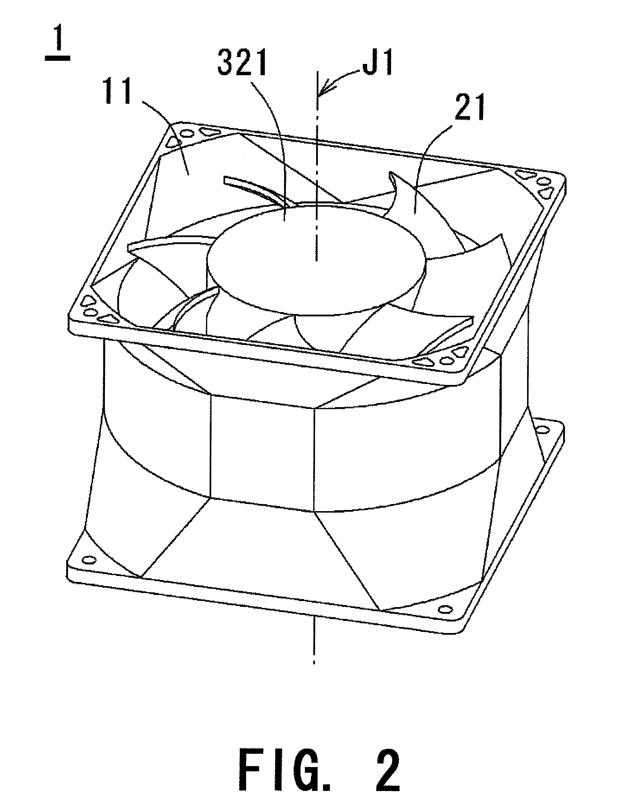
[0027]FIG. 1 is a cross-sectional view of an axial flow fan according to a first preferred embodiment of the present invention. FIG. 2 is a perspective view of the axial flow fan according to the first preferred embodiment of the present invention. FIG. 3 is a perspective view showing a positional relationship between stationary vanes and rotor vanes.

[0028]As shown in FIGS. 1 to 3, the axial flow fan 1 includes a housing 11, a plurality of rotor vanes 21, and a plurality of stationary vanes 4. In this preferred embodiment, seven rotor vanes 21 and nine stationary vanes 4 are provided, for example. The rotor vanes 21 rotate inside the housing 11 and are arranged to be inclined with respect to a central axis J1 of the axial flow fan 1. The stationary vanes 4 are disposed below the rotor vanes 21 in FIG. 2 and are fixed to the housing 11. In this preferred embodiment, the stationary vanes 4 are in the form of thin plates, and the stationary vanes 4 and the rotor vanes 21 are inclined w...

second preferred embodiment

[0049]Next, a description is given on an axial flow fan according to a second preferred embodiment of the present invention. FIG. 9 is a cross-sectional view showing the axial flow fan according to the second preferred embodiment. FIG. 10 is a perspective view showing a modification of the axial flow fan according to the second preferred embodiment. In FIGS. 9 and 10, like structures and components as shown in FIGS. 1 to 7 are designated by like reference numerals in the description below.

[0050]In the axial flow fan according to the second preferred embodiment, on the axially upper end of the sidewall 3112 of the base portion 311 locking portions 3113 are provided in at least four positions in the circumferential direction for locking the circuit board 316, as shown in FIG. 9. The number of positions for disposing the locking portions 3113 is not limited to four, and any number will do so long as the locking portions are provided in more than one positions. The plurality of locking ...


PUM


Abstract

An axial flow fan includes a housing, a plurality of rotor vanes that rotate inside the housing, and a plurality of sheet-like stationary vanes that are disposed below the rotor vanes and fixed to the housing. The axial flow fan includes a motor that is connected to the rotor vanes and rotates the rotor vanes about a central axis. Each stationary vane has a projecting portion projecting axially upward from a sidewall of a base portion. The projecting portion of each stationary vane has an inner side surface on the central axis side. When a stator part is attached to the housing, the outer side surface of a circuit board radially meets the inner side surfaces. The circuit board axially meets the axially upper end surface of the sidewall of the base portion.

Description

BACKGROUND OF THE INVENTION[0001]1. Field of the Invention[0002]The present invention relates to an electric axial flow fan used for sending air.[0003]2. Description of the Related Art[0004]Axial flow fans are conventionally used in electronic devices for sending air to cool heat-generating electronic components so as to suppress temperature rise in the devices. Such an axial flow fan creates an air flow by rotating a plurality of rotor vanes by an electric motor. In order to deal with the increase in the amount of heat generation attendant on the performance improvement of electronic devices, demand is growing for high-speed rotation of such motors.[0005]On the other hand, drive current must be increased in order to rotate the motor at high speeds. This causes increase in the amount of rise in temperature of electronic components on the circuit board or coils of the armature inside the motor, which may affect the performance of the electronic components and the operation of the mot...

Claims


Application Information

Patent Timeline
Patent Type & Authority Applications(United States)
IPC IPC(8): F04D25/08F04D19/00F04D25/06
CPCF04D25/0613F04D29/646F04D29/542
Inventor KATO, YOSHIHISAYAMADA, SUGURU
Owner NIPPON DENSAN CORP
Why Eureka
Try Eureka