Precision Miter Gauge Setting Fixture

a technology setting fixture, which is applied in the field of precision miter gauge setting fixture, can solve the problems of questionable miter angle setting mechanism and accuracy of angular position achievable with such included compass scal

Active Publication Date: 2008-07-31
PATTEE RICHARD
View PDF4 Cites 8 Cited by
  • Summary
  • Abstract
  • Description
  • Claims
  • Application Information

AI Technical Summary

Benefits of technology

[0008]The invented precision miter gauge setting fixture includes a horizontal surface with a miter bar channel that bisects at least one pair of symmetrical arcs of angularly spaced, position receptacles drilled into the surface, where each angular position receptacle of a paired set of arcs, radially centers on a base position receptacle of the other symmetrically paired arc of angular position receptacles. A pair of position posts, one snugly seated in the base position receptacle of one of the paired symmetrical arcs of angular position receptacles, the other snugly seated in one of the angular position receptacles of the other arc of the pair, define the desired angle for setting the angle of a miter gauge fence head relative to the miter bar of a gauge received and sliding in the miter bar channel of the fixture.
[0009]The invented precision miter gauge setting fixture further includes, as an accessory, one or more straight edged, step bars each having a length sufficient to span the radial distance between a base position receptacle of one of a pair of symmetrical arcs of angular position receptacles and each of the angular position receptacles of the other arc of the pair. Each straight edged, accessory, step bar has one or more step detents, each detent incrementally increasing in depth, cut into one or both of its opposite, longitudinal straight edges proximate one or both of its ends for incrementally adding to or subtracting from the angle defined by the respectively seated, position posts, where the angle of the miter fence head of the miter gauge is determined by the angle the free or open longitudinal straight edge of the step dent bar opposite a particular step detent abutting against one or the other of the respectively seated position posts.
[0010]One of the novel aspects of the invented precision, miter gauge setting fixture relates to configuring each pair of symmetrical arcs of angular position receptacles as converging circular arcs such that each angular position receptacle of the respective paired arcs is at the same radial distance from each respective base position receptacle of the other arc.

Problems solved by technology

However, the accuracy of an angular position achievable with such included compass scale, miter angle setting mechanisms is questionable.

Method used


Image

  • Precision Miter Gauge Setting Fixture
  • Precision Miter Gauge Setting Fixture
  • Precision Miter Gauge Setting Fixture

Examples


Embodiment Construction

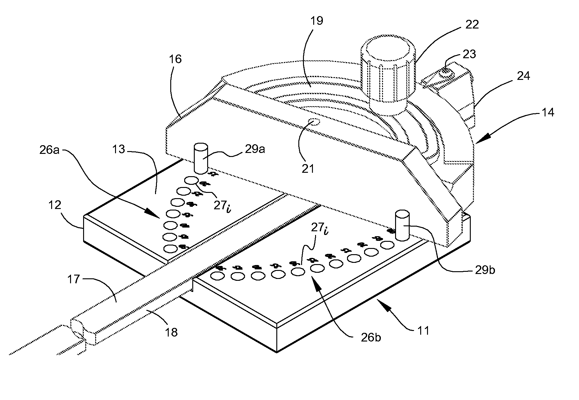
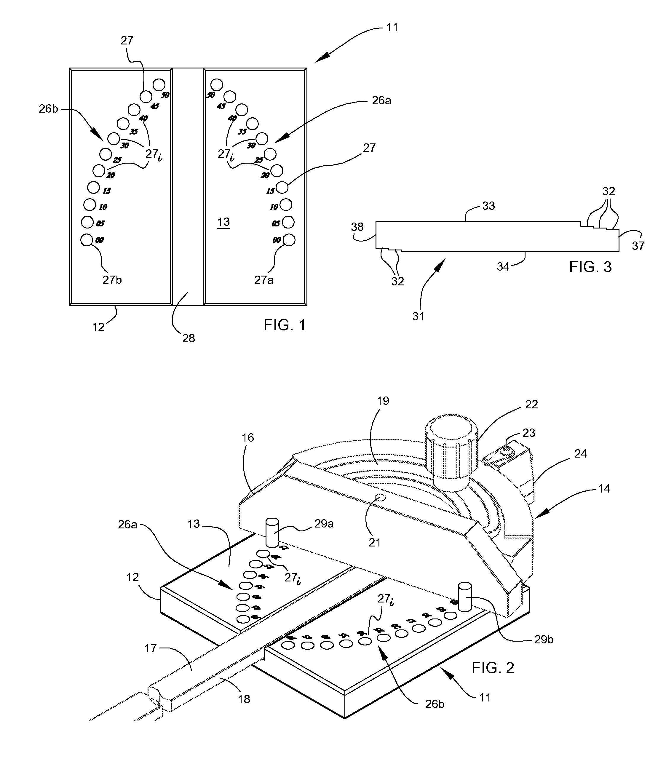
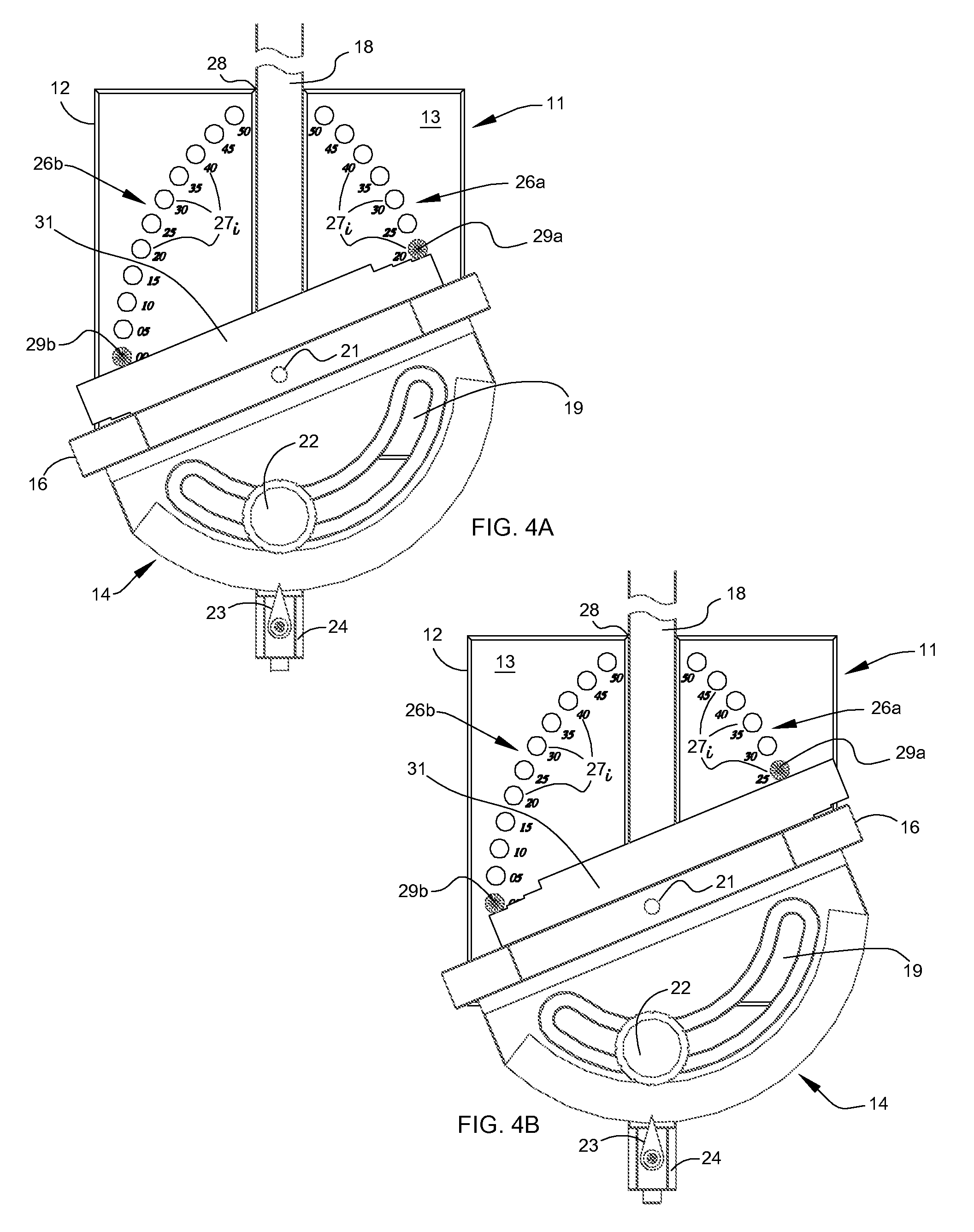
[0018]Looking at the figures, the invented precision, miter gauge setting fixture 11 includes a plate member 12 presenting a flat, horizontal surface 13 large enough to stably support a typical miter gauge 14 with a miter fence head 16 pivotally coupled near an end, to the top 17 of a depending miter bar 18 that extends horizontally out beneath the fence head 16. The fence head 16, as is typical, includes a circular slot 19 concentric with the pivot couple 21 between fence head 16 and the miter bar 18. A compass scale (not shown) indexes the circular slot 19. A knob-screw, position locking mechanism 22 secures or sets the orientation or angle of the miter fence head 16 relative to the miter bar, conventionally indicated by a pointer 23 secured to miter bar 18, here at its back end 24, and the compass scale indexing the circular slot 19.

[0019]As shown in FIG. 1, the plate member 12 of the fixture 11 has a pair of symmetrically converging, circular arcs 26a &26b of angular position re...


PUM

PropertyMeasurementUnit
angleaaaaaaaaaa
angleaaaaaaaaaa
angleaaaaaaaaaa

Abstract

A precision miter gauge setting fixture system is described that includes a horizontal surface with a miter bar channel that bisects at least one pair of symmetrical arcs of angularly spaced, position receptacles drilled into the surface, where each angular position receptacle of a paired set of arcs, radially centers on a base position receptacle of the other symmetrically paired arc of angularly space, position receptacles. A pair of position posts, one snugly seated in the base position receptacle of one of the paired symmetrical arcs of angularly spaced, position receptacles, the other snugly seated in one of the angularly spaced, position receptacles of the other symmetrically paired arc define the desired angle for setting the angle of a miter fence head relative to the miter bar of a miter gauge received and sliding in the miter bar channel.
The described precision miter gauge setting fixture system further includes one or more straight edged, accessory, detent step bars each having a length sufficient to span the radial distance between a base position receptacle of one of a pair of symmetrical arcs of angularly spaced, position receptacles and each of the angularly spaced, position receptacles of the other arc of the pair Each straight edged, accessory, detent step bar also has one or more step detents, each detent incrementally increasing in depth, cut into one or both of its opposite longitudinal straight side edges proximate one or both of its ends for incrementally adding to and subtracting from the angle defined by the respectively seated, position posts, where the angle of the miter fence head of the miter gauge is determined by the angle of the longitudinal straight edge of the step dent bar opposite a particular step detent abutting against one or the other of the respectively seated position posts.

Description

RELATED APPLICATIONS [0001]This application relates to U.S. Provisional Patent Application Ser. No. 60 / 887,327 filed Jan. 30, 2007, and is incorporated herein by reference. Any all benefits accruing by reason of U.S. Provisional Patent Application Ser. No. 60 / 887,327 are claimed.BACKGROUND OF THE INVENTION[0002]1. Field of the Invention[0003]The invention relates to calibration tools and fixtures for precisely setting the angle of miter gauges for table saws, band saws, sanding machines, grinders, shapers, and other primary machines used to shape wood, metal, plastic, fiber and other common stock materials for cutting / forming precise angular edges / surfaces on stock materials, e.g., a picture frame.[0004]2. Description of the Prior Art[0005]Miter gauges for table saws, band saws, sanding machines, grinders, shapers, routers and the like present a vertical fence or miter fence head pivotally secured at the end of a base rail or miter bar that slides within worktable channels cut into ...

Claims


Application Information

Patent Timeline
Patent Type & Authority Applications(United States)
IPC IPC(8): B26D7/06B23Q17/22
CPCB23Q9/005B27G5/023B23Q17/2233Y10T83/6611
Inventor PATTEE, RICHARD
Owner PATTEE RICHARD
Why Eureka
Try Eureka