Profile element pipe for hydraulic bulging, hydraulic bulging device using the element pipe, hydraulic bulging method using the element pipe, and hydraulically bulged product

a technology of hydraulic bulging and profile elements, applied in the field of profile element pipes for hydraulic bulging, can solve the problems of limited configuration of work products which can be obtained, difficulty in applying axial pressing on tapered element pipes, and hydraulic bulging, and achieve the effect of a larger pipe expansion ratio

Inactive Publication Date: 2008-07-31
SUMITOMO PIPE & TUBE CO LTD +2
View PDF15 Cites 9 Cited by
  • Summary
  • Abstract
  • Description
  • Claims
  • Application Information

AI Technical Summary

Benefits of technology

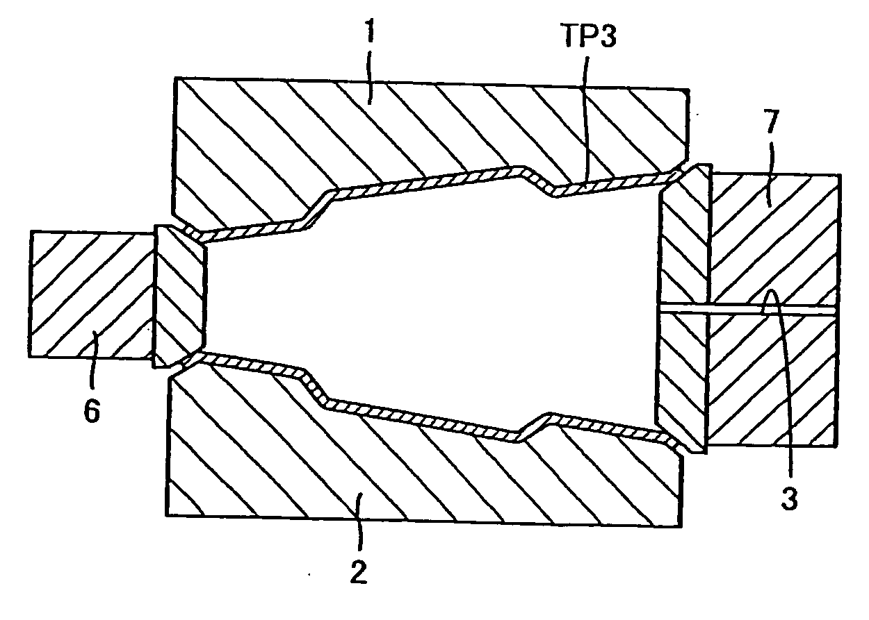
[0027]The present invention has been made taking the above-mentioned conventional problems into consideration, and the object of the present invention is to provide a profile element pipe for hydraulic bulging, a hydraulic bulging device using the element pipe, a hydraulic bulging method using the element pipe, and hydraulically bulged product, wherein in hydraulic bulging using the profile element pipe having various cross sectional shapes in the axial direction, pressing is enabled from the pipe ends in the axial direction in addition to loading internal pressure on the element pipe, thereby enabling a larger pipe expansion ratio to be achieved.
[0032]As described above, in the hydraulic bulging, a larger pipe expansion ratio can be obtained than before, and the joining with other parts can be easily performed.

Problems solved by technology

Further, the hydraulic bulging has a problem attributable to a shape of the element pipe.
As described above, even if an intricate configuration having different axial cross-sectional shapes can be obtained as one of the merits of the hydraulic bulging, the configuration of a worked product which can be obtained is limited.
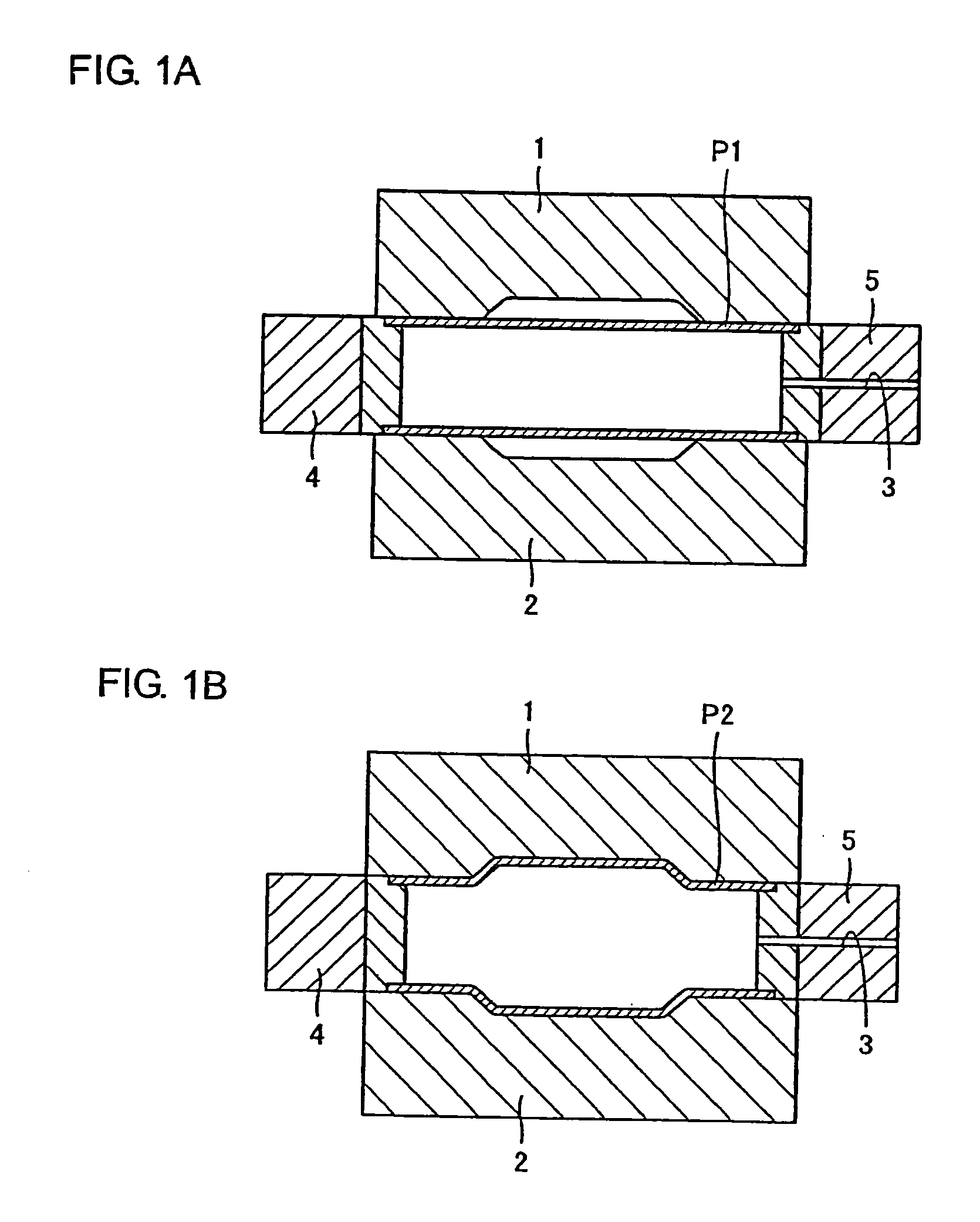
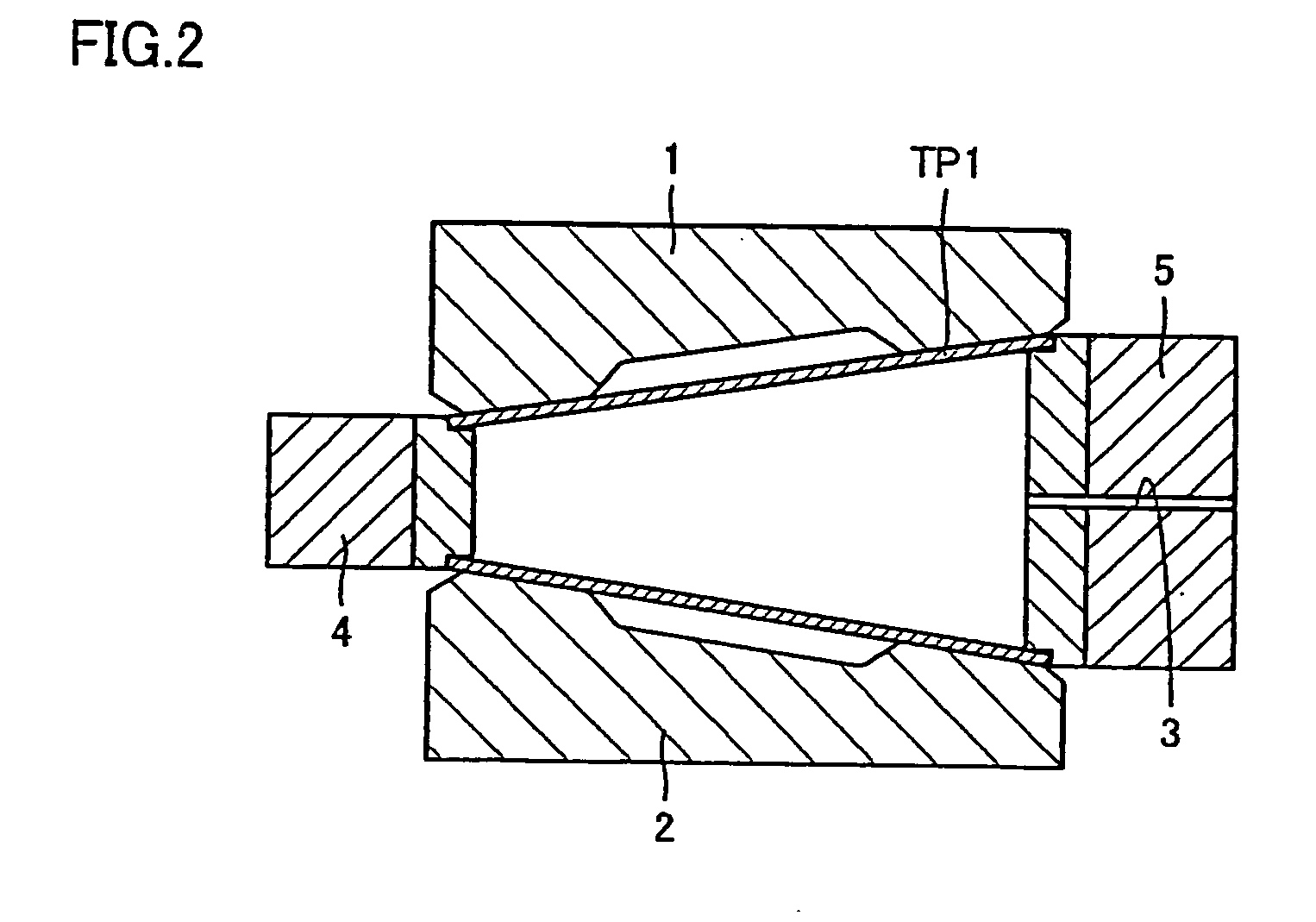
However, when hydraulic bulging is performed by using a tapered element pipe whose cross-sectional shape varies in the axial direction, in case of using a pressing or pushing tool for the straight element pipe shown in FIG. 1, it is found difficult to apply the axial pressing on the tapered element pipe.
However, as a pressing tool 4 advances into forms 1 and 2 with the axial pressing, insufficient restriction of inner and outer surfaces of the tapered element pipe TP1 by the pressing tool 4 side take places, thus likely leading up to seal leakage occurs.
However, since axial pressing cannot be performed, hydraulic bulging is generally completed only by loading internal pressure without axial pressing.
Therefore, in the hydraulic bulging, a merit of using the tapered element pipe is not in fact fully utilized.
When hydraulic bulging is performed in a conventional tapered element pipe, there is a problem which arises when a hydraulically bulged product is joined with another member, other than the problem that axial pressing is difficult.
Thus, since accuracy cannot be ensured in welding and joining with another member, the joining with another member or the like is not easy.
Further, when an end of the pipe is socketed into another part and connected thereto, that is a socket connection, the accuracy cannot be ensured as well.
Thus positioning of the tapered element pipe becomes difficult.

Method used


Image

  • Profile element pipe for hydraulic bulging, hydraulic bulging device using the element pipe, hydraulic bulging method using the element pipe, and hydraulically bulged product
  • Profile element pipe for hydraulic bulging, hydraulic bulging device using the element pipe, hydraulic bulging method using the element pipe, and hydraulically bulged product
  • Profile element pipe for hydraulic bulging, hydraulic bulging device using the element pipe, hydraulic bulging method using the element pipe, and hydraulically bulged product

Examples


Embodiment Construction

[0053]FIGS. 5A to 5B are cross-sectional views showing an example of the shape of tapered pipe constituting a profile element pipe of the present invention. A profile element pipe 11 for hydraulic bulging of the present invention is a profile element pipe to be provided for hydraulic bulging, has a peripheral length with an outer diameter gradually increasing or decreasing over axial length from one axial side toward the other thereof and forms parallel parts 11a, 11b on at least one pipe-end (both pipe ends of a small diameter side and a large diameter side have parallel parts in the examples shown in FIGS. 5A and 5B). The parts 11a and 11b are considered to be end portions of the profile element pipe that are parallel to each other since they are each aligned with an axis of the profile element pipe 11. Because the outer diameter of the profile element pipe portion that is between the parallel end parts increases or decreases along its peripheral length, the profile element pipe h...


PUM

PropertyMeasurementUnit
lengthaaaaaaaaaa
outer diameteraaaaaaaaaa
axial forceaaaaaaaaaa

Abstract

According to a bulging device and a bulging method using a profile element pipe, for example, even when a profile steel pipe having a cross sectional shape varying in the axial direction as in a tapered pipe is hydraulically bulged, a bulging in which an internal pressure loading and an axial pressing are combined with each other can be performed to provide a larger expansion ratio than a conventional case and a joining and socket connection thereof to the other part can also be easily performed.

Description

[0001]This is a continuation in part application of application Ser. No. 11 / 806,531 filed on Jun. 1, 2007, which is a divisional application Ser. No. 11 / 123,196 filed on May 6, 2005, which is a continuation of International Patent Application No. PCT / JP2003 / 014284, filed Nov. 10, 2003.BACKGROUND OF THE INVENTION[0002]1. Field of the Invention[0003]The present invention relates to a profile element pipe for hydraulic bulging, a hydraulic bulging device using the profile element pipe, a hydraulic bulging method using the profile element pipe, and a hydraulically bulged product subjected to the hydraulic bulging.[0004]2. Description of the Related Art[0005]A hydraulic bulging has more merits as compared with other forming or forming methods. For example, since a profile element pipe can be hydraulically bulged to such an intricate configuration part having different cross-sections in the longitudinal direction of the product, machine parts, which require welding and joining in a conven...

Claims


Application Information

Patent Timeline
Patent Type & Authority Applications(United States)
IPC IPC(8): B21D26/02
CPCB21D26/033Y10T29/49805B21D26/047B21D26/045
Inventor TOMIZAWA, ATSUSHIKOJIMA, MASAYASU
Owner SUMITOMO PIPE & TUBE CO LTD
Why Eureka
Try Eureka